

 ENG
ENG
 English
 русский
 Español
 Türk
Türk

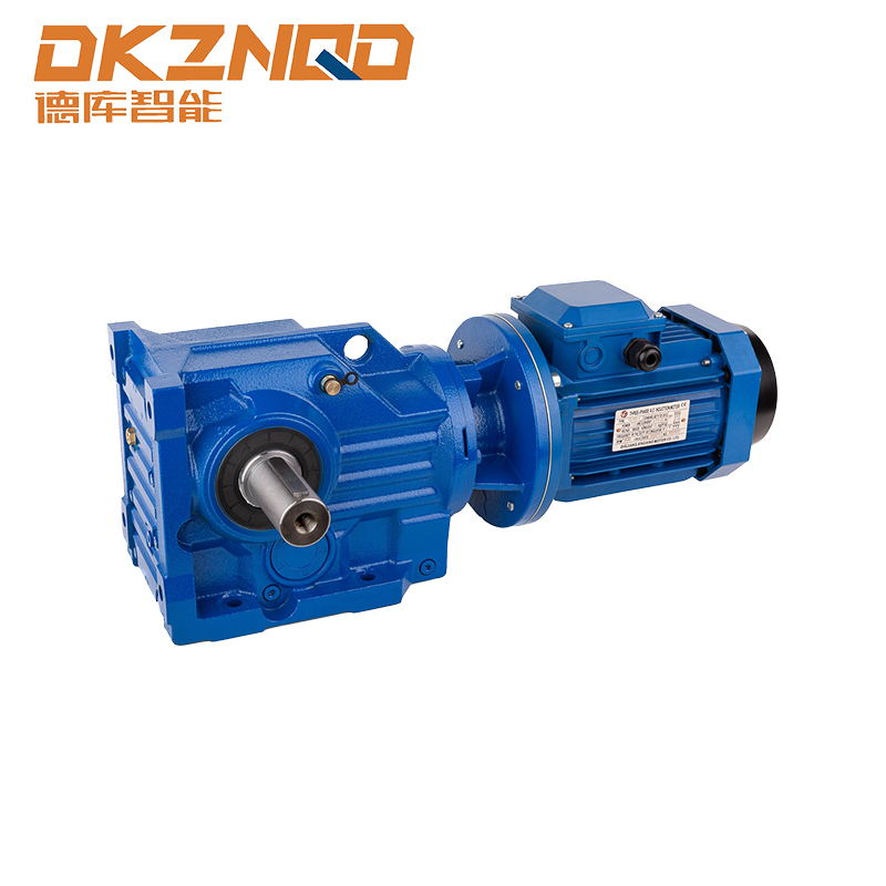
Why Helical Gear Motor Selection Determines Long-Term Drive Efficiency
A production line rarely fails because of the motor alone. More often, the weak point sits at the interface between the motor shaft and the gearbox, where backlash, misalignment, or an undersized reduction ratio quietly eats into throughput. Helical gear motors solve this by combining the prime mover and the reduction stage into a single housed unit, which removes one coupling point and one source of alignment error compared with a separate motor and gearbox arrangement.
The helical tooth form itself is the reason these units run quieter and transmit more load per unit volume than straight spur designs. Because the teeth engage at an angle rather than along a straight line, contact is gradual and distributed across a longer path, which spreads the load and reduces the impact noise associated with tooth entry and exit. This article works through the mechanical reasoning behind that efficiency gain, how backlash and mounting position affect real-world performance, and how to match a r series helical gear motor, an f series helical gear motor, or a k series helical gear motor to a specific application rather than a general category.
Getting this selection right matters more on a running line than it does on paper, because a gear motor that is technically capable of handling a load but poorly matched to the mounting geometry or duty cycle will still cost more in energy and maintenance over a multi-year service life than a correctly specified unit purchased at a slightly higher upfront price. The sections below are organized around the decisions that actually change field outcomes, starting with the tooth geometry itself and moving through mounting, lubrication, and manufacturing tolerance.
How the Helical Gear Tooth Angle Changes Power Transmission
In a straight spur gear, the full width of a tooth contacts its mating tooth simultaneously. That instant engagement produces a sharp mechanical impulse every time a new tooth pair enters mesh, which is the primary source of the whine associated with older gearbox designs. A helical gear cuts the teeth at an angle to the axis of rotation, so contact starts at one edge of the tooth and rolls progressively across the face width as the gears turn.
This progressive engagement has three measurable effects on a gear motor drivetrain:
- Load is shared across more than one tooth pair at any given instant, which lowers peak stress on an individual tooth and extends service life under repeated loading.
- Noise generation drops meaningfully, often by several decibels compared with an equivalent spur design running the same load, because there is no abrupt tooth-to-tooth impact.
- Running smoothness improves at higher input speeds, which matters for applications where the motor operates near its rated RPM for extended periods.
The tradeoff is axial thrust. Because the teeth are cut at an angle, meshing generates a force along the shaft axis in addition to the radial and tangential forces present in a spur gear. Helical gear motor housings account for this with thrust bearings sized for the specific helix angle used, which is one reason gearbox housings cannot simply be swapped between series without checking the bearing rating.
Matching Series Design to Application Load Profile
Manufacturers organize helical gear motor product lines into series because a single housing geometry cannot efficiently cover the full range from light conveyor drives to heavy mixing or crushing loads. Each series typically targets a torque band, a mounting style, and a set of ratio steps, so choosing correctly starts with the duty cycle rather than the catalog page. A useful starting question is not which series looks most capable on paper, but which shaft arrangement the surrounding equipment already dictates, since retrofitting a frame to accept a different shaft orientation is usually far more expensive than paying slightly more for the correctly configured housing from the outset.
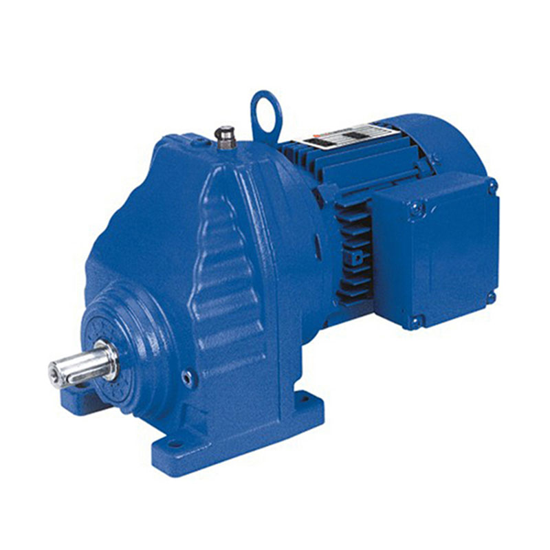
R Series Helical Gear Motor
Built around a compact coaxial housing, this series suits applications where the output shaft needs to sit in line with the motor shaft, such as vertical conveyors or stirring equipment where floor space is limited. Ratio steps are typically finer at the lower end of the range, which helps when a process needs precise speed matching rather than raw torque.
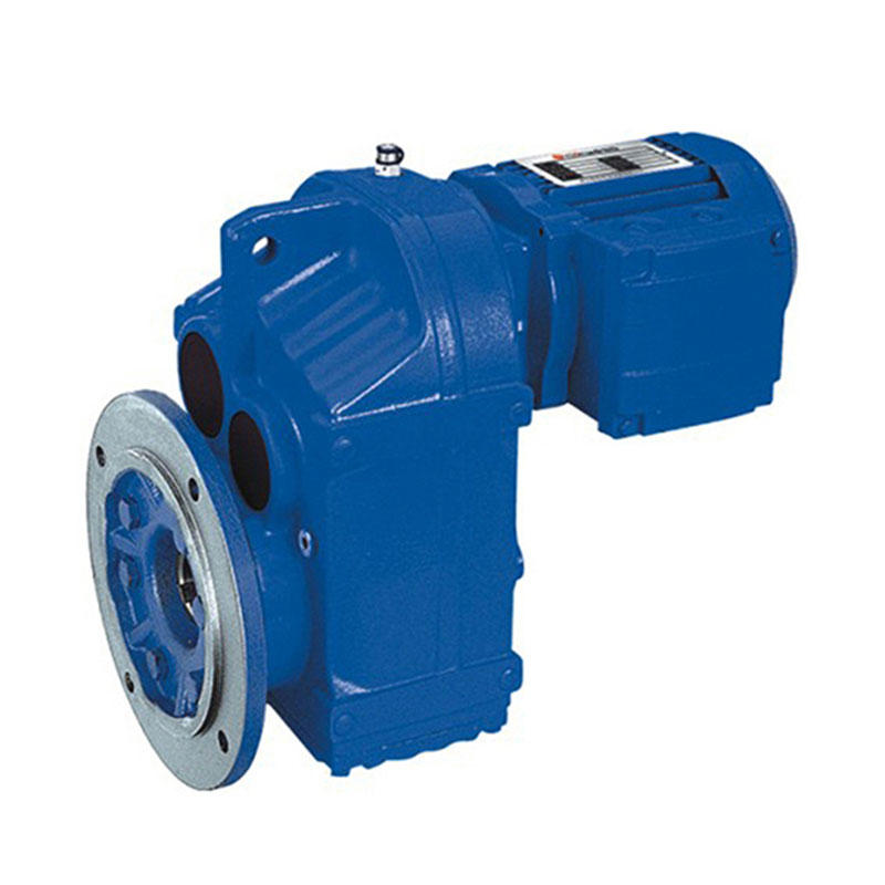
F Series Helical Gear Motor
The parallel shaft layout used in this series keeps input and output shafts side by side rather than in line, which simplifies belt or chain drive integration on equipment such as packaging lines and material handling systems where the output shaft needs to sit at a fixed height above a frame.
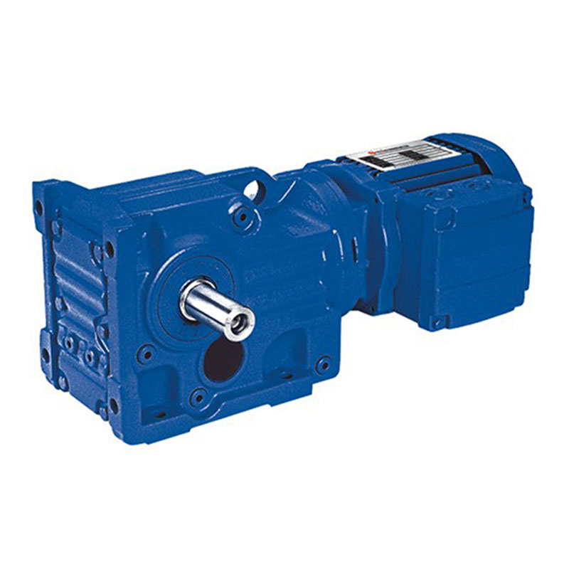
K Series Helical Gear Motor
Combining helical and bevel gear stages, this series changes the direction of power transmission by roughly ninety degrees within a single housing. That makes it a common choice for agitators, cranes, and installations where the drive needs to turn a corner without adding a separate right-angle gearbox.
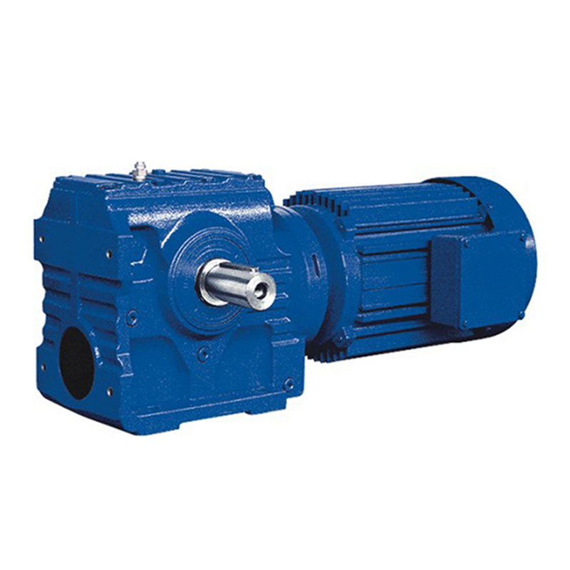
S Series Helical Gear Motor
This series pairs a helical input stage with a worm gear output stage, which delivers a higher single-unit reduction ratio than a purely helical design while keeping the housing footprint relatively small. The tradeoff is a lower peak efficiency than an all-helical unit, since worm meshes involve more sliding contact than rolling contact.
Comparing Structural and Performance Characteristics Across Series
The table below summarizes the practical differences that should drive a selection decision. Efficiency figures represent typical single-stage helical mesh performance and will vary with ratio, load, and lubrication condition.
| Characteristic | Coaxial Helical | Parallel Shaft Helical | Helical-Bevel | Helical-Worm |
|---|---|---|---|---|
| Shaft arrangement | In line | Offset parallel | Right angle | Right angle |
| Typical single stage efficiency | 96 to 98 percent | 96 to 98 percent | 94 to 96 percent | 82 to 90 percent |
| Best suited load type | Light to medium continuous | Medium to heavy continuous | Medium with directional change | Light to medium, space limited |
| Relative housing footprint | Small | Medium | Medium | Small |
| Typical backlash class | Standard to reduced | Standard to reduced | Standard | Standard |
Efficiency numbers compound across stages. A two stage helical unit running at 97 percent per stage delivers roughly 94 percent overall, while a helical-worm combination at 88 percent single stage plus a helical pre-stage at 97 percent lands closer to 85 percent overall. Over a multi-shift operating year, that gap translates directly into electricity cost, which is why high duty cycle installations tend to favor all-helical designs even when the worm option would fit a smaller footprint.
Mounting Position and Its Effect on Bearing Life
Gear motor catalogs list several standard mounting positions, and the temptation is to treat this as a purely geometric choice. In practice, mounting orientation changes how lubricant distributes inside the housing and how load is carried by the bearings, which affects service life even when the torque and speed ratings are identical on paper.
Vertical shaft orientations concentrate more weight on the lower bearing and require enough oil volume that the upper gear teeth stay lubricated as the unit runs, since splash lubrication depends on rotation constantly redistributing oil upward. When a unit originally rated for foot mounting is installed vertically without checking the oil fill level for that orientation, the upper stage can run under-lubricated even though the sump appears full from a foot-mounted perspective. Reviewing the mounting-specific fill chart before installation, rather than assuming a single oil level applies to every orientation, is one of the more overlooked steps in commissioning.
Understanding Backlash and When It Actually Matters
Backlash is the small rotational play between mating teeth, intentionally built in so the gears do not bind as temperature changes cause the housing and gears to expand at different rates. For most conveyor, mixing, and general material handling applications, standard backlash classes are appropriate and cause no measurable process issue.
Backlash becomes a design concern in three specific situations:
| Application Type | Why Backlash Matters | Recommended Approach |
|---|---|---|
| Indexing or positioning drives | Play translates directly into position error each time direction reverses | Specify reduced backlash class and verify with a dial indicator at final assembly |
| Frequent reversing duty | Repeated impact loading at direction change accelerates tooth wear | Select a series rated for reversing duty and derate the torque slightly |
| Synchronized multi-motor lines | Unequal backlash across units causes drift between synchronized axes | Source all gear motors on the line from the same backlash class specification |
Outside of these cases, chasing a reduced backlash class adds cost without a corresponding benefit, since normal continuous rotation in one direction never engages the play in a way that affects the driven equipment.
Motor to Gearbox Coupling and Where Efficiency Gets Lost
Even a well-designed gear stage cannot compensate for a poor motor-to-gearbox interface. Three factors determine how much of the motor's rated output actually reaches the driven load:
- Shaft alignment between the motor rotor and the input pinion. Integrated gear motor housings remove this variable almost entirely because the motor is factory fitted to the housing, unlike a separately coupled motor and reducer where field alignment tolerances add a variable loss.
- Bearing preload on the input shaft, which needs to be set within the manufacturer tolerance. Too little preload allows shaft movement under load, and too much increases friction losses and shortens bearing life.
- Lubricant viscosity grade relative to ambient operating temperature. A lubricant that is too viscous for cold-start conditions increases churning losses during startup, while one that is too thin for high ambient temperatures increases wear on tooth flanks over time.
Reviewing the technical data for a specific helical-bevel unit against the actual ambient temperature range of the installation site, rather than assuming a single lubricant grade covers all climates, prevents a large share of the premature bearing failures reported in field service data.
Specification Checklist Before Placing an Order
Confirming the following points before finalizing a purchase order avoids the most common causes of a mismatch between catalog rating and field performance.
- Confirm the required output torque at the actual operating speed, not just at the motor nameplate speed, since torque and speed move inversely through a reduction stage.
- Verify the mounting position and check that the oil fill specification matches that orientation.
- Check ambient temperature range, including any enclosed or outdoor exposure, against the standard lubricant rating.
- Determine whether the duty cycle includes frequent reversing or start-stop operation, which affects both backlash class and thermal rating.
- Confirm shaft output type, whether solid shaft, hollow shaft, or shrink disc, matches the connecting equipment.
- Review the service factor against actual peak load, including any shock loading during startup.
Manufacturing Precision and Its Long-Term Effect on Noise and Wear
Two gear motors with identical published specifications can perform noticeably differently in the field if one was cut and heat treated to a tighter tolerance grade than the other. Gear tooth accuracy is typically graded on standardized scales that quantify profile error, pitch error, and helix angle deviation. Units cut to a finer grade run quieter and generate less vibration at the same load, but more importantly, they tend to maintain that performance over a longer service interval because the initial contact pattern is closer to ideal, spreading wear more evenly across the tooth face from the first day of operation rather than concentrating it on a few high points that were slightly out of tolerance.
Heat treatment consistency matters just as much as the initial cut. Case hardening depth that varies across a gear blank creates soft spots that wear faster under load, eventually changing the tooth profile enough to increase backlash beyond its original specification. This is one reason field-measured backlash on an aging gearbox often exceeds the nameplate value even when the unit has never been overloaded.
Frequently Asked Questions
Q1: What is the practical difference between a helical gear motor and a standard geared motor?
The term geared motor covers any combination of a motor and a reduction stage, including worm, bevel, planetary, and helical designs. A helical gear motor specifically uses angled-cut teeth for the reduction stage, which generally delivers higher efficiency and lower noise than a worm design at a comparable price point, though it requires more precise housing tolerances to manufacture.
Q2: Can a foot mounted unit be installed vertically without modification?
It depends on the series and the specific oil fill chart provided by the manufacturer. Some housings use a common internal cavity design across all orientations and only require an adjusted oil level, while others use orientation-specific breather and drain plug positions that must be changed for a vertical installation to function correctly.
Q3: How much does reduction ratio affect overall efficiency?
Higher ratios generally require more reduction stages, and each additional stage introduces its own mesh losses. A single stage helical unit commonly reaches the mid to high nineties in percentage efficiency, while a triple stage unit needed for a very high ratio can fall into the high eighties simply because three sets of mesh losses compound.
Q4: Is a higher service factor always the safer choice?
A higher service factor provides more margin against shock loading and thermal buildup, but oversizing a gear motor well beyond the actual load can push the motor into a less efficient part of its operating curve and increases both purchase cost and physical footprint without a corresponding benefit for a steady, well-characterized load.
Q5: How often should gear oil be checked in a sealed helical gear motor?
Sealed units are typically filled for life or for a long service interval, but ambient temperature extremes, water ingress through a damaged seal, or extended operation above the rated duty cycle can degrade oil faster than the standard interval assumes. A visual inspection of seals and a periodic oil sample check remain good practice even on units marketed as maintenance free.
 05 Jun,2025