

 ENG
ENG
 English
 русский
 Español
 Türk
Türk

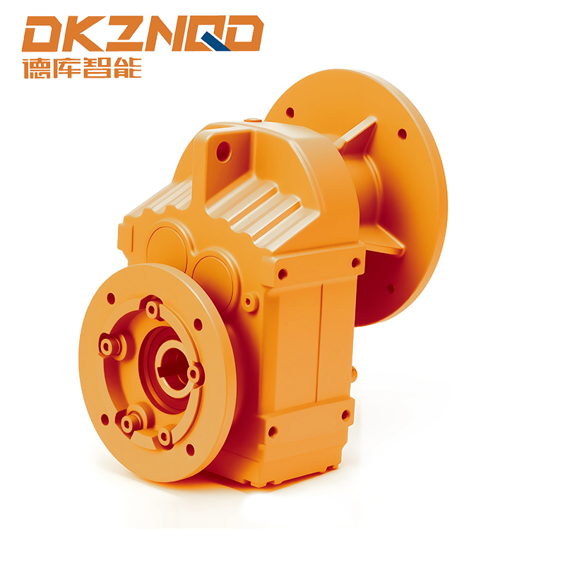
Understanding NEMA Frame Numbering Logic
A NEMA frame number is not a marketing label. It is a coded reference to physical mounting geometry, primarily shaft height, that lets a maintenance technician swap motors across manufacturers without redrawing a baseplate. Once the numbering logic is understood, an electric motor frame size chart stops looking like a wall of numbers and starts working like a lookup table for real dimensions.
The core rule is simple: divide the first two digits of the frame number by four, and the result is the shaft centerline height above the base, measured in inches. A 143T frame therefore has a 3.5 inch shaft height, and a 256T frame has a 6.25 inch shaft height. This single relationship is the backbone of every nema motor frame sizes table published by standards bodies and equipment integrators alike.
- First two digits: shaft height divided by 4, in inches
- Third digit: coded reference to the distance between mounting feet (frame length)
- Letter suffix: mounting configuration, such as T for standardized shaft dimensions or C for close-coupled face mounting
Frames sharing the same first two digits, such as 143T and 145T, have identical shaft heights but different foot spacing, which is why a drop-in replacement motor must match the full frame designation, not just the leading numbers.
Historically, frame numbering evolved through several revisions before the T-frame standard became dominant. Older U-frame and earlier non-standardized designs used different proportional rules, which is why a technician pulling a motor from equipment installed decades ago may find a frame number that does not follow the divide-by-four logic at all. When replacing legacy motors, it is worth checking the nameplate date and cross-referencing an archived frame table rather than assuming the current T-frame rule applies retroactively.
The practical value of this numbering system shows up most clearly during emergency replacements. A maintenance team facing an unplanned motor failure on a production line does not have time to draft new mounting hardware. Reading the frame designation off the nameplate and matching it against a published nema motor sizes reference lets the team confirm, in minutes, whether a stocked spare or a same-day supplier order will physically fit the existing base, coupling, and conduit routing.
Standard NEMA Motor Frame Sizes and Dimensions Chart
The table below summarizes commonly specified frames across small and mid-size industrial motors. Dimensions are approximate nominal values in inches, consistent with published NEMA MG 1 tables, and are intended for preliminary layout work rather than final drawing approval.
| Frame | Shaft Height (D) | Shaft Diameter (U) | Base to Center (D) | Foot Length (2E) | Typical HP Range |
|---|---|---|---|---|---|
| 48 | 3.00 in | 0.500 in | 3.00 in | 3.75 in | 1/4 to 3/4 |
| 56 | 3.50 in | 0.625 in | 3.50 in | 4.50 in | 1/3 to 3 |
| 143T | 3.50 in | 0.875 in | 3.50 in | 5.50 in | 1 to 1.5 |
| 145T | 3.50 in | 0.875 in | 3.50 in | 6.50 in | 1.5 to 3 |
| 182T | 4.50 in | 1.125 in | 4.50 in | 7.50 in | 3 to 5 |
| 184T | 4.50 in | 1.125 in | 4.50 in | 8.50 in | 5 to 7.5 |
| 213T | 5.25 in | 1.375 in | 5.25 in | 9.50 in | 7.5 to 10 |
| 215T | 5.25 in | 1.375 in | 5.25 in | 11.00 in | 10 to 15 |
| 254T | 6.25 in | 1.625 in | 6.25 in | 12.50 in | 15 to 20 |
| 256T | 6.25 in | 1.625 in | 6.25 in | 14.50 in | 20 to 25 |
Reading this motor frame dimensions chart correctly means recognizing that shaft height and shaft diameter scale together in fixed steps, so a facility standardizing on a handful of frame families can predict coupling and keyway requirements before a replacement motor even arrives.
Foot length, listed above as the 2E dimension, is often the value that trips up an otherwise straightforward replacement. Two motors with an identical shaft height, such as 143T and 145T, will bolt to bases with different foot-hole spacing, so a technician who only checks shaft height before ordering a spare can end up with a motor that will not align with the existing baseplate slots. Keeping a printed copy of the full dimension table near the parts crib, rather than relying on memory of the leading digits, avoids this repeat mistake.
Horsepower ranges shown in the table are typical rather than absolute. Motor designers can push a given frame toward the upper end of its horsepower range using improved winding materials or higher-efficiency lamination stacks, so it is common to see two motors in the same frame separated by a noticeable difference in rated output. When torque, not just horsepower, is the limiting factor for an application, checking the nameplate torque rating alongside the frame dimensions gives a more complete picture than horsepower alone.
Base-to-center dimension, listed as D in most tables, matters for vertical clearance in tight installations such as underground pump stations or enclosed equipment skids. Confirming this dimension before ordering prevents a situation where a correctly framed motor cannot physically clear an overhead obstruction once it is bolted into place.
NEMA C-Face Motor Mounting Types Explained
The C suffix identifies a motor built for close-coupled, face-mounted installation, most commonly paired with pumps, gearboxes, and blowers where the driven equipment bolts directly to the motor front rather than connecting through a flexible coupling and separate bearing support.
56C Frame Motor Dimensions
The 56c frame motor dimensions designation is one of the most frequently specified small C-face sizes because it covers a wide fractional and low integral horsepower range while keeping a compact bolt circle. A typical 56C motor uses a 4.5 inch bolt circle diameter with four tapped mounting holes and a 3.375 inch spigot register diameter, allowing precise concentric alignment with the mating pump or reducer housing.
184TC Frame Motor
Moving up in horsepower, the 184tc frame motor combines the 184T shaft height and foot pattern with a larger 8.5 inch bolt circle and 6.625 inch spigot register, matching mid-size gearbox input flanges used in conveyor drives, mixers, and agitator systems.
A practical field note: TC frames retain standard T-frame feet in addition to the face mount, so the same motor can often be installed either as a foot-mounted unit or bolted face-first to driven equipment, depending on the base already in place.
Beyond the C-face family, D-face and P-base variants exist for applications where the driven equipment needs a flanged mount without a shaft extension protruding past a fixed register, or where a projected base pattern is required for certain pump configurations. These are less commonly specified in general industrial work but appear frequently in fluid handling and vertical turbine pump packages, where axial alignment tolerance is tighter than typical foot-mounted installations allow.
Spigot register fit is worth emphasizing because it does more mechanical work than the bolt circle itself. The register centers the motor shaft precisely on the driven equipment's input bore, while the bolt circle only secures the assembly once alignment is already established. A register with excessive clearance, even by a few thousandths of an inch, can introduce enough radial runout to shorten coupling or seal life on a close-coupled pump, which is why manufacturers hold tighter tolerances on register diameter than on most other frame dimensions.
Visualizing the C-Face Mounting Pattern
The diagram below illustrates the key measurement points referenced on any NEMA C-face specification sheet: bolt circle diameter, spigot register diameter, and shaft extension length.
Metric vs NEMA Motor Frames: Key Differences
Facilities sourcing equipment internationally frequently need to cross-reference NEMA frames against IEC metric frames. The two systems are built on different base units and are not directly interchangeable without an adapter or a full baseplate redesign.
| Characteristic | NEMA Frame | IEC Metric Frame |
|---|---|---|
| Sizing unit | Inches | Millimeters |
| Shaft height basis | Frame number divided by 4 | Frame number equals shaft height directly |
| Bolt pattern standard | NEMA MG 1 | IEC 60072 |
| Common shaft finish | Inch-based keyways | Metric keyways |
| Typical region of use | North America | Europe, Asia, most export markets |
A frequent point of confusion is that some IEC frame numbers appear numerically close to NEMA equivalents, such as a 132M metric frame sitting near a 145T NEMA frame in horsepower range, but the actual shaft height, bolt pattern, and keyway are all different, so cross-shipping parts between the two systems without verified drawings is a common cause of failed installations.
Keyway profile is another area where the two systems diverge in ways that are easy to overlook. NEMA shafts typically use a square or rectangular key sized to fractional inch standards, while IEC shafts use metric key stock sized in whole millimeters with a different depth-to-width ratio. A coupling hub bored and keyed for one system will rarely accept a shaft from the other without machining, even when the raw shaft diameter happens to measure close in both systems.
Procurement teams working across both standards benefit from maintaining a simple cross-reference sheet listing frame number, shaft height, shaft diameter, and keyway dimension side by side for both systems, rather than relying on horsepower rating as the primary matching criterion. Horsepower is the least reliable field for cross-referencing because efficiency class, duty cycle, and ambient temperature rating all shift the horsepower a given frame can deliver, independent of its physical mounting dimensions.
Industrial Motor Interchange Chart Considerations
An industrial motor interchange chart is only useful when it accounts for more than frame number. Before treating two motors as interchangeable, verify the following secondary factors, since matching frame size alone does not guarantee a drop-in fit.
- Shaft length and keyway width, since two motors sharing a frame number can still ship with different usable shaft lengths
- Conduit box location and orientation relative to the mounting feet
- Bearing type, particularly where the driven load imposes side or thrust loading beyond standard ball bearing ratings
- Enclosure type, since an open drip-proof motor and a totally enclosed fan-cooled motor in the same frame will have different overall lengths and cooling airflow requirements
- Mounting foot hole pattern, which can vary slightly between motors built to older and newer revisions of the same standard
Duty cycle rating deserves its own mention on any interchange checklist. A motor stamped for continuous duty and one stamped for intermittent duty may share an identical frame, yet the intermittent-duty unit will overheat if pressed into a continuous application, regardless of how well the mechanical fit matches. Interchange decisions based purely on frame geometry, without cross-checking the duty cycle and insulation class on the nameplate, are a common source of premature winding failure after an otherwise successful physical installation.
Voltage and frequency compatibility round out the non-dimensional checks that belong alongside any frame comparison. Two motors can share an identical frame designation while being wound for different voltage classes or line frequencies, so an interchange chart used for procurement should always list electrical nameplate data next to the mechanical frame data, not as a separate lookup step performed later in the process.
When a motor is paired with a gear reducer, frame compatibility extends into the reducer input as well. For close-coupled drivetrains, matching a correctly framed motor to a unit such as the f series parallel shaft helical gearmotor requires confirming that the reducer input flange, shaft diameter, and rotation direction all align with the selected motor frame before final assembly.
Selecting Frame Size for Gearmotor and Reducer Pairing
Frame selection becomes more involved once a reducer enters the drivetrain, because the reducer input geometry, not just the motor shaft, determines whether a given frame will physically bolt up. Parallel shaft helical designs are a common choice where a compact inline footprint and high efficiency at moderate reduction ratios are priorities.
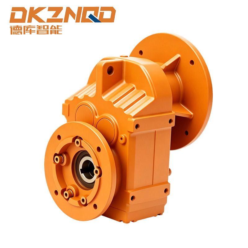
A parallel shaft helical gearmotor assembly typically integrates a NEMA or IEC frame motor directly onto a helical gear stage, so the mounting interface, shaft diameter, and rotation direction all need to be checked against the reducer's input specification sheet before ordering, rather than assumed from frame number alone.
Facilities standardizing on a single reducer family across multiple production lines often find it easier to fix the motor frame size first, then select the reducer input option that matches, rather than working in the reverse order.
Output torque and service factor are the two figures most likely to be overlooked when a gearmotor assembly is specified purely from motor frame size. A correctly framed motor bolted to an undersized reducer will still turn, but the reducer's gear stage can wear prematurely under sustained load, particularly in applications with frequent starts, shock loading, or extended operation near the top of the rated torque band. Reviewing the reducer's service factor against the actual duty cycle of the driven equipment, rather than against nameplate horsepower alone, is the more reliable sizing approach.
Mounting orientation also affects gearmotor selection in ways that a motor-only frame chart will not capture. A parallel shaft helical unit intended for horizontal mounting may require a different lubrication fill level, or a modified breather location, if the same housing is instead mounted vertically. Confirming the intended mounting orientation with the reducer specification sheet before finalizing motor frame selection avoids a costly field modification after installation.
Enclosure Type and Its Effect on Frame Selection
Frame number governs mounting geometry, but enclosure type governs overall physical envelope and cooling behavior, and the two are frequently confused during specification. An open drip-proof motor and a totally enclosed fan-cooled motor built on the same frame designation will still share identical shaft height, bolt pattern, and foot spacing, yet differ in overall length, external fan shroud diameter, and airflow clearance requirements.
Open Drip-Proof Enclosures
Open drip-proof designs rely on ambient air drawn directly across the windings for cooling, which keeps the overall motor length shorter but restricts use to relatively clean, dry indoor environments where airborne dust or moisture will not accumulate inside the winding cavity.
Totally Enclosed Fan-Cooled Enclosures
Totally enclosed fan-cooled designs isolate the windings from the surrounding atmosphere and rely on an external shaft-mounted fan and shroud to move air across ribbed housing fins. This adds length and sometimes width to the motor relative to an open drip-proof unit of the same frame, which matters when clearance around the motor is already tight.
| Enclosure Type | Cooling Method | Typical Environment | Relative Length |
|---|---|---|---|
| Open Drip-Proof | Direct ambient airflow | Clean, dry indoor | Shorter |
| Totally Enclosed Fan-Cooled | External fan over ribbed housing | Dusty, damp, outdoor-adjacent | Longer |
| Totally Enclosed Non-Ventilated | Passive radiation and convection | Low duty cycle, contaminated air | Similar to TEFC |
Because enclosure choice changes overall envelope dimensions without changing the mounting frame itself, any procurement checklist built around standard motor frame dimensions should treat enclosure type as a mandatory companion field, not an optional note, particularly for retrofit projects where the replacement motor must fit inside an existing equipment guard or coupling cover.
Common Frame Size Mistakes and How to Avoid Them
| Mistake | Consequence | Prevention |
|---|---|---|
| Matching only the leading two digits | Foot spacing mismatch, motor will not bolt to existing base | Always confirm full frame designation including third digit and suffix |
| Ignoring enclosure type when swapping | Overall length mismatch, conduit box interference | Cross check enclosure code alongside frame number |
| Assuming IEC and NEMA frames interchange | Bolt pattern and shaft diameter mismatch | Use manufacturer conversion tables, not frame number proximity |
| Overlooking shaft length on C-face units | Insufficient engagement in coupling or reducer bore | Verify usable shaft length against the driven equipment specification |
Most frame-related installation failures trace back to relying on a single dimension in isolation. A thorough check against the full standard motor frame dimensions sheet, covering shaft, bolt pattern, and enclosure together, prevents the majority of field fitting problems before a motor is ever uncrated.
Frequently Asked Questions
Q1: How do I quickly estimate shaft height from a NEMA frame number?
Divide the first two digits of the frame number by four. The result is the shaft centerline height in inches above the mounting base.
Q2: What does the T suffix mean on a NEMA frame designation?
The T suffix indicates a standardized frame introduced to unify shaft and mounting dimensions across manufacturers, replacing earlier non-standardized frame series.
Q3: Can a 56C frame motor be installed without a face-mount driven component?
Yes, many 56C motors include both foot mounting holes and a face-mount pattern, allowing either configuration depending on the application.
Q4: Is it safe to substitute an IEC motor for a NEMA frame motor if the horsepower matches?
Horsepower alone is not sufficient. Shaft diameter, bolt pattern, and keyway standards differ between the two systems, so a direct substitution usually requires an adapter plate or coupling change.
Q5: Why do two motors with the same frame number sometimes have different shaft lengths?
Frame standards fix shaft height and diameter, but usable shaft extension length can vary by manufacturer within the allowed tolerance, so it should always be confirmed against the application drawing.
 05 Jun,2025