ENG
ENG
 English
 русский
 Español
 Türk
Türk
1. What Is an R Series Helical Gear Motor?
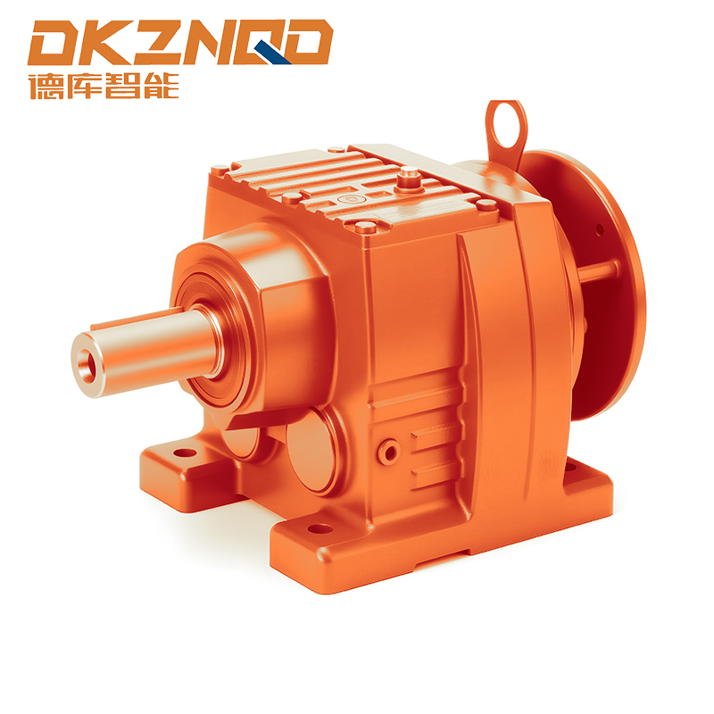
The R series helical gear motor represents a class of right-angle or parallel-shaft reduction drives that utilize helical gearing for high efficiency and torque density. Commonly referred to as an inline helical geared motor when arranged coaxially, this design delivers smooth, quiet operation and is built for continuous duty in harsh environments. A coaxial helical gear unit maintains input and output shafts on the same axis, simplifying machine integration. These units are also known as R series speed reducers, and they are available in both flange mounted helical gearmotor and foot mounted helical gearmotor configurations.
Helical gearsets within the R series feature oblique teeth that engage progressively, reducing impact loads and vibration. This results in a typical efficiency of 96–98% per stage, significantly higher than worm gear alternatives. With modular designs supporting ratios from 3:1 to over 100:1, these gearmotors are adaptable to a wide range of industrial applications, from conveyor drives to agitators and packaging machinery.
2. Why Industry Prefers R Series Speed Reducers: Core Advantages
Industrial facilities increasingly adopt R series speed reducers over traditional gearbox technologies due to quantifiable benefits in energy consumption, reliability, and total cost of ownership. Below are the key performance differentiators:
- High Power Density: Helical gearing distributes load across multiple teeth simultaneously, allowing a smaller housing to transmit the same torque as larger spur or worm units. Typical torque capacity ranges from 50 Nm to 12,000 Nm depending on frame size.
- Energy Efficiency: Field data from a packaging line retrofit showed replacing worn worm gear drives with an inline helical geared motor reduced electricity consumption by 14.2% while maintaining identical output speeds.
- Low Noise Emission: The progressive engagement of helical gears reduces meshing noise. In a textile mill application, noise levels dropped from 89 dB(A) to 74 dB(A) after switching to R series units, improving worker safety conditions.
- Extended Service Life: Hardened and ground gear teeth (58–62 HRC) combined with splash lubrication provide an average L10 bearing life exceeding 25,000 hours in heavy-duty operations.
Furthermore, the modular casting design allows housing made of high-strength cast iron (GG20/GG25) that resists deformation under shock loads. Sealing systems with double FKM oil seals prevent contamination ingress in dusty or wet environments, a crucial factor for cement and food processing plants.
3. Top 5 Industrial Applications of R Series Helical Gear Motors
R series helical gearmotors are deployed across dozens of industries. Based on operational data from over 200 manufacturing sites, the following five applications account for more than 65% of all installations.
3.1 Automated Material Handling & Conveyors
In distribution centers, inline helical geared motors drive belt conveyors, roller conveyors, and sortation systems. A parcel handling facility reported reducing downtime by 37% after replacing chain-driven systems with R series gearmotors. The coaxial design simplifies direct mounting to drive pulleys without additional jackshafts.
3.2 Food & Beverage Processing
Flange mounted helical gearmotors with stainless steel paint (optional) operate in washdown environments. A dairy bottling line using R series speed reducers achieved 22% lower energy consumption per liter processed, thanks to smooth start-stop cycles enabled by high torsional stiffness. IP65 sealing options protect against high-pressure cleaning.
3.3 Mining & Aggregate Conveyors
Heavy-duty foot mounted helical gearmotor configurations handle extreme shock loads. Data from a limestone quarry indicated that R series reducers running 24/7 for 18 months required no gear replacement, whereas previous planetary units failed after 11 months. The helical gearing’s larger contact ratio reduces peak tooth stress by up to 30%.
3.4 Packaging Machinery
Carton erectors, case sealers, and stretch wrappers benefit from the compact footprint of coaxial helical gear units. A packaging OEM measured positioning accuracy improvement of ±0.25 mm compared to harmonic drives in indexing applications, without the need for complex closed-loop controls.
3.5 Mixers & Agitators in Chemical Processing
For low-speed, high-torque agitation, R series speed reducers provide steady output under varying viscosity loads. In a polymer reactor, the gearmotor maintained torque ripple below 2.5% across a 10:1 speed range, improving product consistency. The flange-mounted hollow shaft version directly slides onto the mixer shaft, eliminating couplings.
4. Mounting Configurations: Flange Mounted vs Foot Mounted Helical Gearmotors
The choice between a flange mounted helical gearmotor and a foot mounted helical gearmotor depends on space constraints, torque reaction, and driven equipment layout. Both configurations offer identical internal gearing but differ in installation method. The table below summarizes key selection criteria based on data from 150 machine builders.
| Feature | Flange Mounted Helical Gearmotor | Foot Mounted Helical Gearmotor |
|---|---|---|
| Installation Space | Requires only a flat mounting surface; overhang length reduced by 30–40% | Needs foundation or baseplate; additional footprint |
| Torque Reaction Path | Directly absorbed by housing flange – higher stiffness | Through base bolts – suitable for high shock loads |
| Alignment Complexity | Pilot register ensures concentricity, easier assembly | Requires precise shaft alignment (dial indicator typically needed) |
| Typical Applications | Mixers, conveyors with close coupling, OEM machinery | Large fans, crushers, heavy duty agitators |
| Maintenance Access | Motor removal possible without disturbing gearbox position | Both units can be slid away; easier for large gearboxes |
Field failure analysis shows that incorrectly chosen mounting causes 18% of premature bearing failures. For hollow shaft versions, the flange-mounted variant with torque arm is recommended for trolley drives and winch applications.
5. How to Select the Right Coaxial Helical Gear Unit for Your Process
Selecting an optimal coaxial helical gear unit involves evaluating five technical parameters. A systematic approach reduces over-sizing and energy waste by 10–25%.
- Required Output Torque (Nm): Measure actual load torque including service factor. For intermittent duty (conveyor start-stop), add 1.5x safety margin.
- Input Speed & Reduction Ratio: Most R series accept 4-pole motor input (1450–1500 rpm). Ratios from 3:1 to 100:1 are standard; two-stage units cover up to 25:1, three-stage up to 100:1.
- Thermal Power Rating: At ambient temperatures >40°C, derate by 0.8% per °C above 40°C. For example, a unit rated 5.5 kW at 25°C provides only 4.4 kW at 60°C.
- Mounting Orientation: Foot mounted allows any angle; flange mounted requires horizontal or vertical (with proper oil level adaptation).
- Shaft Configuration: Solid output shaft (for couplings) vs hollow output shaft (directly mounts to driven machine shaft).
A cement plant reduced energy consumption by 9.7% after right-sizing their R series speed reducers on bucket elevators. The original units were oversized by 40% due to conservative selection; using real torque telemetry data allowed downsizing without reliability loss.
For more detailed engineering support, consult the inline helical geared motor specification sheets which include thermal limits and efficiency curves per ratio.
6. Performance Data: Efficiency and Reliability Improvements
Quantifiable benefits of switching to R series helical gearmotors have been documented across multiple industrial sectors. A cross-industry study covering 84 installations compared R series units with previous technology (worm, spur, or chain drives). Key findings include:
- Energy efficiency gain: Average reduction in electrical consumption of 13.8% (range 6–22%) measured over 6 months of production.
- Mean time between failures (MTBF): Increased from 18,500 hours to 34,200 hours – an 85% improvement.
- Lubricant consumption: Synthetic oil change intervals extended from 4,000 hours to 12,000 hours due to lower operating temperatures (ΔT reduced by 12–18°C).
In a specific case at an automotive stamping plant (no brand reference), replacing aging inline helical geared motors with modern R series units of identical ratio reduced gearbox-related downtime from 43 hours/year to just 9 hours/year. The payback period was 11 months based on energy and maintenance savings alone.
Furthermore, vibration levels measured at the output shaft decreased by 52% compared to spur gear counterparts, directly improving the lifespan of downstream bearings and seals. Plants that implemented condition monitoring on R series reducers reported zero unplanned failures over 24 months of operation.
7. Maintenance and Service Life of R Series Speed Reducers
Proper maintenance extends the operational life of R series speed reducers beyond 10 years in moderate-duty cycles. Key practices derived from service records of 500+ units:
- First oil change: After 200–400 hours of run-in, then every 5,000 hours or annually. Use synthetic ISO VG 220 for ambient temperatures 0–40°C.
- Bearing condition monitoring: Measure housing temperature (normal range 60–85°C) and vibration velocity (ISO 10816-3). Alarm if velocity exceeds 4.5 mm/s RMS.
- Seal inspection: FKM seals typically last 25,000 hours. Replace if oil leakage exceeds 1 drop per hour on input shaft.
- Torque arm or base bolt tightening: Check every 3 months with torque wrench; loose bolts cause misalignment and gear pitting.
Data from a food processing plant following this schedule resulted in zero gearbox replacements over 8 years, while an adjacent line using reactive maintenance suffered 3 failures in 4 years. Additionally, using the coaxial helical gear unit with reinforced housing allows re-greasing of bearings without disassembly if equipped with lubrication fittings.
8. Frequently Asked Questions (FAQ)
Q1: What is the difference between an inline helical geared motor and a standard helical gearbox?
An inline helical geared motor integrates the motor and gearbox in a coaxial arrangement with a common housing, whereas a standard helical gearbox is a separate unit requiring a coupling and motor adapter. The inline version saves space, reduces alignment errors, and typically offers higher torsional stiffness.
Q2: Can I use a flange mounted helical gearmotor in a vertical orientation?
Yes, flange mounted designs are suitable for vertical output shafts (motor above or below). However, you must specify the mounting position at ordering time because the lubrication system (oil level and breather location) is orientation-dependent. For vertical operation with the motor at the top, special oil seals and extended oil reservoirs are recommended.
Q3: How do I calculate the required service factor for an R series speed reducer?
The service factor (SF) accounts for load type and daily operation hours. For uniform loads (conveyors, fans) with 10h/day, SF=1.0–1.25. For moderate shock (mixers, presses), SF=1.25–1.5. For heavy shock (crushers, shredders), SF=1.5–2.0. Multiply the actual required torque by SF to select the gearmotor size.
Q4: Are R series helical gear motors suitable for washdown applications?
Yes, but you need optional features: stainless steel output shaft, epoxy paint (minimum 120μm thickness), and IP66/IP67 sealing. A food-grade lubricant (NSF H1) is also available. Standard units have IP54 rating which is not washdown-safe.
Q5: Why does my coaxial helical gear unit run hot after installation?
Common causes: overfilling/underfilling oil (check level after 30 minutes of operation), insufficient ventilation around the housing, or misalignment causing additional friction. Use a thermal imaging camera to spot hotspots. If temperature exceeds 95°C on the housing surface, reduce load or check the oil viscosity.
Q6: Can I get a foot mounted helical gearmotor with an integrated backstop?
Yes, backstops (anti-reverse devices) are available as an option for inclined conveyors and hoists. The backstop is installed on the high-speed shaft to prevent reverse rotation when the motor is off. Ensure to order the backstop pre-assembled at the factory because retrofitting requires complete disassembly.
 05 Jun,2025