ENG
ENG
 English
 русский
 Español
 Türk
Türk
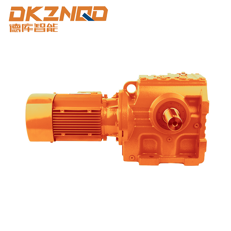
Introduction to S Series Helical Worm Gearmotors
The S series helical worm gearmotor is widely used in industrial machinery due to its compact design, high torque transmission, and reliability under diverse operating conditions. Understanding the mounting positions (M1-M6) of these gear units is essential for engineers and system designers who aim to achieve optimal performance and ensure mechanical compatibility.
This article delves into the specific mounting positions available for the S series gear units, exploring their configurations, advantages, and practical applications in various industries.
Overview of Mounting Positions (M1-M6)
S series gear units are designed to support multiple mounting orientations, categorized as M1 through M6. Each mounting position corresponds to a unique arrangement of the input and output shafts relative to the motor housing. Choosing the correct mounting position impacts:
- Operational efficiency and torque delivery
- Ease of installation in constrained spaces
- Maintenance accessibility and safety compliance
Below is a detailed explanation of each mounting position and its applications:
M1 Position: Horizontal Foot Mounting
The M1 mounting position refers to a horizontal installation with the gear unit mounted on a base or platform. The output shaft is parallel to the base, making it ideal for:
- Conveyors and material handling systems
- Packaging machinery where floor-level mounting is preferred
- Applications requiring stable alignment under high torque loads
Advantages of M1 mounting include easy access for lubrication and inspection, and compatibility with standardized base dimensions commonly used in industrial gear setups.
M2 Position: Horizontal Flange Mounting
M2 configuration involves horizontal installation with a flange at the output shaft end for direct coupling. This orientation is suitable for:
- Direct integration into rotating machinery without additional brackets
- Pumps, compressors, and fan drives where shaft alignment is critical
- Applications requiring compact installation in limited horizontal space
The M2 flange mount reduces vibration transmission and simplifies installation when compared to foot-mounted alternatives.
M3 Position: Vertical Shaft Down
In the M3 configuration, the output shaft points downward. This is particularly useful when connecting to vertically oriented machinery, such as:
- Mixers and agitators in chemical or food processing plants
- Vertical conveyors and elevators
- Applications requiring direct downward drive with minimal shaft extension
This mounting orientation requires careful consideration of lubrication and sealing due to gravity-driven oil distribution along the gears.
M4 Position: Vertical Shaft Up
M4 is the inverse of M3, where the output shaft points upward. It is commonly applied in:
- Bucket elevators and vertical conveyors with upward motion
- Industrial mixers where torque transmission needs to move material upward
- Situations where the gear unit is installed below a connected mechanism for compact vertical alignment
The M4 position necessitates optimized lubrication routing to ensure even oil distribution across worm and helical gears.
M5 Position: Horizontal Shaft Side-Mounted
M5 represents a horizontal orientation where the gear unit is mounted on its side. This position is chosen for:
- Machines with space constraints requiring lateral gear installation
- Integration into conveyor systems with offset drive points
- Applications needing improved alignment between motor and driven shaft with minimal footprint
Side mounting can enhance mechanical stability in compact systems but may require custom brackets or supports.
M6 Position: Flange Vertical
M6 configuration combines vertical shaft orientation with flange mounting. Key benefits include:
- Facilitates direct connection to vertical motors or pumps
- Ideal for installations with height limitations or where floor space is constrained
- Improved torque distribution in high-load vertical applications
M6 positioning often demands precise alignment and may benefit from vibration-damping mounts to ensure long-term operational stability.
Practical Considerations for Mounting Selection
Selecting the correct mounting position is more than a mechanical decision—it involves consideration of the operational environment, accessibility, and maintenance requirements. Engineers should consider:
- Load direction and torque requirements
- Lubrication distribution and gear oil retention
- Space constraints and integration with existing machinery
- Ease of inspection, serviceability, and safety compliance
Adhering to these considerations ensures optimal performance and extended lifespan of the gear unit.
Comparison Table of S Series Mounting Positions
| Mounting Position | Shaft Orientation | Typical Applications | Installation Considerations |
| M1 | Horizontal | Conveyors, packaging machines | Stable base mounting, easy maintenance |
| M2 | Horizontal, flange | Pumps, fans, compressors | Vibration reduction, compact installation |
| M3 | Vertical down | Mixers, vertical conveyors | Gravity-assisted oil distribution needed |
| M4 | Vertical up | Bucket elevators, mixers | Optimized lubrication routing required |
| M5 | Horizontal, side-mounted | Lateral conveyor drives | May require custom brackets |
| M6 | Vertical, flange | Vertical pumps, compact vertical drives | Precision alignment, vibration damping |
Conclusion
Understanding the M1-M6 mounting positions for the S series helical worm gearmotor enables engineers to make informed decisions regarding installation, torque transmission, and system longevity. Each position offers unique advantages tailored to specific operational needs, ensuring that the gear unit performs reliably under diverse industrial scenarios.
Proper selection, combined with consideration for lubrication, alignment, and accessibility, can significantly enhance the performance and maintenance efficiency of industrial gear systems.
FAQ
Q1: What is the difference between M1 and M2 mounting positions?
M1 is horizontal foot-mounted, while M2 uses a flange for horizontal mounting, suitable for direct coupling with machinery and improved vibration control.
Q2: Can an S series gear unit operate in vertical positions?
Yes, M3, M4, and M6 allow vertical installation, with careful attention to lubrication and alignment to ensure reliable operation.
Q3: Which mounting position is best for space-constrained setups?
M5 (horizontal side-mounted) and M6 (vertical flange) are ideal for compact installations where floor space is limited.
Q4: Do mounting positions affect maintenance requirements?
Yes, positions like M3 and M4 require careful lubrication routing, while M1 and M2 allow easier access for inspection and servicing.
 05 Jun,2025