ENG
ENG
 English
 русский
 Español
 Türk
Türk
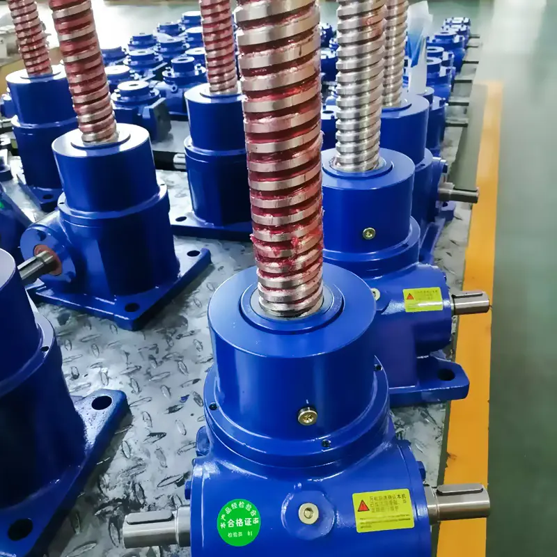
In the field of industrial equipment transmission, the SWL series worm gear screw lift is widely used in various lifting operations due to its compact structure, strong load-bearing capacity, and smooth transmission. During the installation of the SWL series lift, the verticality of the screw is a key factor in ensuring the normal operation of the equipment, extending its service life, and ensuring the accuracy of the operation. If the verticality of the screw deviates, it will cause a large lateral force when the equipment is running, aggravate component wear, reduce transmission efficiency, and even cause safety accidents. Therefore, it is very important to master scientific and standardized installation methods to ensure the verticality of the screw.
1.Preparations before installation
Equipment and component inspection
Before installing the SWL series worm gear screw lift, first conduct a comprehensive and detailed inspection of the equipment and related components. Focus on checking whether there are scratches, bumps, deformations and other defects on the surface of the screw, because even minor damage may gradually expand during operation, affecting the verticality and overall performance of the screw. At the same time, check whether the meshing surface of the worm gear is smooth and flat, and whether there are burrs or foreign objects attached to ensure the smoothness of its transmission. In addition, the dimensional accuracy and processing quality of the matching nuts, bearings, connecting flanges and other components should also be checked one by one to avoid the verticality after installation being affected by the errors of the components themselves.
Installation foundation evaluation
The quality of the installation foundation is directly related to the maintenance of the verticality of the screw. Before installation, the flatness, strength and stability of the installation foundation need to be strictly evaluated. Use a high-precision level to measure the installation foundation plane, and require its flatness error to be controlled within a very small range, generally not exceeding the specified standard. If there is a large height difference in the foundation plane, it can be corrected by grinding, milling or adding a pad of appropriate thickness to ensure that the installation foundation plane is flat and stable. At the same time, it is necessary to ensure that the bearing capacity of the installation foundation meets the operating requirements of the SWL series lift to prevent the verticality of the screw from changing due to foundation settlement or deformation during the operation of the equipment.
Installation tool preparation
To ensure installation accuracy, necessary high-precision installation tools need to be prepared. For example, use a laser level or a high-precision level to assist in determining the installation reference plane and verticality; equip with a suitable torque wrench to ensure that the bolt tightening force of each connection part is uniform and consistent to avoid the screw installation tilt due to uneven force. In addition, measuring tools such as vernier calipers and micrometers should be prepared so that key dimensions can be measured and adjusted at any time during the installation process.
2. Key steps and controls during the installation process
Base installation positioning
The base of the SWL series lift is the foundation for supporting the entire equipment, and the accuracy of its installation positioning plays a decisive role in the verticality of the screw. First, place the base on the processed installation foundation, use a laser level or level, and use the installation reference line or reference plane as a reference to accurately adjust the horizontal position of the base. By placing a level at multiple key parts of the base, repeatedly adjust the thickness and position of the pad under the base to control the horizontal error of the base within the allowable range. Then, use a torque wrench to tighten the connecting bolts between the base and the foundation in sequence according to the specified torque. During the tightening process, the principle of symmetry and step-by-step tightening should be followed to ensure that the base is evenly stressed and prevent it from shifting during the tightening process.
Assembly of worm gear and lead screw
When assembling the worm gear and lead screw, pay special attention to the coaxiality of the two, because the error of coaxiality will directly reflect the verticality of the lead screw. First, place the lead screw steadily on a dedicated assembly platform to ensure the horizontality of the platform. Then, slowly insert the worm gear assembly into the lead screw. During the insertion process, use a dial indicator and other measuring tools to monitor the coaxiality error of the two in real time, and fine-tune the position of the worm gear assembly to control the coaxiality error within a reasonable range. At the same time, during the assembly process, ensure that the worm gear and the lead screw are well lubricated, and apply an appropriate amount of special lubricant to reduce friction resistance and avoid deformation of components caused by heat generated by friction, which affects the installation accuracy.
Connection and fixation of lead screw and base
When the worm gear and lead screw are assembled, connect them as a whole to the installed and positioned base. During the connection process, ensure that the center line of the lead screw is perpendicular to the installation reference line of the base. Verticality detection can be performed by using a laser level or plumb bob at different heights of the lead screw. If verticality deviation is found, it can be corrected by adjusting the thickness of the pad between the base and the foundation, or by fine-tuning the position of the connection flange between the screw and the base. During the adjustment process, it is necessary to measure and fine-tune the screw several times until the verticality of the screw meets the installation requirements. After the adjustment is completed, use a torque wrench to tighten the connecting bolts between the screw and the base according to the specified torque. The principle of symmetry and step-by-step tightening should also be followed to ensure that the connection is firm and the force is even.
Installation and coordination of other components
After the screw and the base are connected and fixed, other supporting components such as protective devices and limit switches need to be installed. When installing these components, be careful to avoid affecting the verticality of the adjusted screw. For example, when installing the protective device, ensure that its mounting bracket is parallel to the screw and no additional lateral force should be applied to the screw. For the installation of the limit switch, ensure that its trigger position is accurate and that the screw will not be displaced or deformed during the installation process. At the same time, check whether the connection between the components is tight and whether there is interference between the moving parts to ensure that the entire SWL series lift can run normally and smoothly after installation.
3. Inspection and adjustment after installation
Verticality inspection
After installation, the verticality of the lead screw needs to be fully inspected. A variety of inspection methods can be used to verify each other to ensure the accuracy of the inspection results. Common inspection methods include the use of laser theodolites, high-precision levelers, or electronic levelers. Taking the laser theodolite inspection as an example, the laser theodolite is placed at a suitable distance from the SWL series lift, and the instrument is adjusted so that the laser beam it emits is parallel to the installation reference line. Then, the laser beam is projected to different heights of the lead screw to measure the distance deviation between the lead screw surface and the laser beam. By measuring in multiple directions, the verticality data of the lead screw at different angles is obtained to determine whether it meets the design requirements. If the inspection result exceeds the allowable error range, the lead screw needs to be readjusted.
Adjustment and calibration
According to the inspection results, targeted adjustments are made to the lead screw with verticality deviation. If the deviation is small, it can be adjusted by fine-tuning the thickness of the pad between the base and the foundation, or by properly loosening and re-tightening the connecting bolts. During the adjustment process, the verticality changes of the lead screw should be monitored in real time, and the deviation should be gradually adjusted to the allowable range. If the deviation is large, it may be necessary to disassemble the relevant parts, reassemble and adjust them. After the adjustment is completed, a comprehensive verticality test should be performed again to ensure that the adjustment effect meets the requirements. At the same time, the connection parts involved in the adjustment process should be re-tightened, and the installation status of each component should be checked to ensure that the entire SWL series lift is installed firmly and operates reliably.
Ensuring the verticality of the screw during the installation of the SWL series worm gear screw lift is a systematic and delicate work. It requires full preparation before installation, strict control of every key step in the installation process, and comprehensive inspection and adjustment after installation. Only in this way can the screw of the SWL series lift have good verticality, laying a solid foundation for the stable operation, efficient operation and long life of the equipment.
 05 Jun,2025