ENG
ENG
 English
 русский
 Español
 Türk
Türk
Introduction
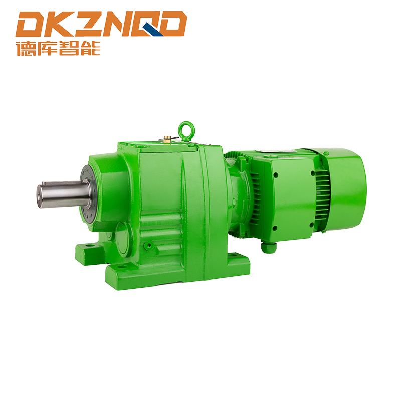
In the realm of industrial machinery, the drive for efficiency and reliability is paramount. The r series helical geared motor stands as a cornerstone in this pursuit, renowned for its robust construction, operational smoothness, and high degree of efficiency. However, the true strength of this component lies not just in its standard off-the-shelf performance but in its extensive adaptability. For original equipment manufacturers (OEMs), system integrators, and buyers, the ability to specify a drive solution that fits a unique spatial, mechanical, and operational requirement is a critical advantage.
Understanding the Foundation: The R Series Helical Geared Motor
Before delving into customization, it is important to understand the base product. An r series helical geared motor is an integral component that combines an electric motor with a helical gear reducer. The term “helical” refers to the design of the gear teeth, which are cut at an angle to the axis of rotation. This angle allows for multiple teeth to be in mesh at any given time, compared to other gear types. This fundamental design principle results in several inherent benefits: significantly quieter operation due to a smoother engagement process, a higher load-carrying capacity for a given size, and superior transmission efficiency, which translates into lower energy consumption and reduced operating costs over time. The r series is characterized by its modular design philosophy, which allows for a high degree of interchangeability between components and a wide array of configuration possibilities. This modularity is the bedrock upon which its customization options are built, enabling engineers and buyers to tailor the unit precisely to their mechanical and spatial constraints without compromising on the core performance attributes that define the series.
The Critical Role of Mounting Configurations
The method by which a geared motor is fixed to its supporting structure and connected to the driven machine is a fundamental aspect of its application engineering. The mounting configuration determines the physical integration, alignment, stability, and often the accessibility of the unit for maintenance. Selecting the incorrect mount can lead to installation difficulties, misalignment-induced wear, excessive vibration, and premature failure. For the r series helical geared motor, the two primary and most requested mounting styles are the foot mount and the flange mount. Each style serves distinct purposes and offers unique advantages, making them suitable for different operational environments and industry requirements. In some complex applications, a combination of both mounts may be specified to provide exceptional rigidity and support. The choice between these options is one of the first and most important decisions a designer or buyer must make when specifying a motor for a new piece of equipment or a retrofit project, impacting everything from the machine’s footprint to its long-term serviceability.
Foot Mount Configuration: The Traditional Workhorse
The foot-mounted r series helical geared motor is one of the most traditional and widely recognized configurations in industrial settings. In this design, the gearbox housing is equipped with integral feet, typically located at the base of the unit, which feature precisely machined mounting holes. These feet allow the entire assembly to be securely bolted onto a flat, horizontal surface, such as a machine bedplate, a concrete foundation, or a fabricated steel frame.
The primary advantage of the foot mount is its inherent stability and simplicity. Once securely fastened, the unit is firmly anchored, resisting torsional forces generated during start-up and operation. This configuration is often favored in applications where the motor is situated in a dedicated, accessible location and where the driven machine is separately supported. Common examples include large conveyor drives, industrial pumps, agitators, and certain types of extrusion machinery. The design allows for relative ease of installation and alignment, though shimming may be required to ensure perfect leveling. Furthermore, a foot-mounted design typically provides good accessibility to the motor for electrical connections and to the gearbox for lubrication points.
However, a consideration with foot-mounted units is the potential for baseframe distortion. If the mounting surface is not perfectly flat and rigid, tightening the holding bolts can induce stresses into the gearbox housing, potentially leading to misalignment of the internal components and bearing failures. Therefore, specifying a foot-mounted r series helical geared motor necessitates ensuring that the host structure is sufficiently robust and flat to accommodate it without introducing such distortions. This mount is ideal for applications prioritizing straightforward, robust support over saving space.
Flange Mount Configuration: The Space-Saving Solution
In contrast to the foot mount, the flange-mounted r series helical geared motor is designed for applications where space is at a premium or where the driven equipment is designed to directly accept a flanged input. Instead of feet, this configuration features a large, machined flange on the output side of the gearbox. This flange is bolted directly to a corresponding flange on the driven machine, such as a reducer, a pulley, or the housing of the equipment itself.
The most significant benefit of the flange mount is its compactness and weight distribution. By eliminating the need for a separate baseplate or foundation, the entire drive package becomes more integrated and space-efficient. This makes it an excellent choice for applications within packaging machinery, mobile equipment, and enclosed systems where the footprint is severely limited. The direct coupling also creates a very rigid connection between the motor and the load, which can enhance the overall torsional stiffness of the drive train and improve responsiveness.
There are several standard flange designs available for the r series, ensuring compatibility with a wide range of equipment. Common types include a plain flange, which requires the user to provide through-bolts, or a flange with threaded holes. The precise machining of the flange face and pilot diameter is critical, as it ensures accurate concentric alignment with the driven shaft, minimizing the risk of radial or axial load misalignment. It is important to note that while the flange supports the weight of the motor itself, the entire assembly’s weight and the reaction forces from the drive are transferred to the host machine’s structure. Therefore, the host must be designed to handle these loads without flexing. For many OEMs, the flange mount is the preferred choice for building compact, original equipment.
Combined Mounting: Achieving Maximum Rigidity
For the most demanding applications subject to high shock loads, severe vibrations, or where absolute positional stability is non-negotiable, a combination foot and flange mount can be specified for the r series helical geared motor. This hybrid approach leverages the benefits of both configurations. The flange provides the direct, rigid connection to the driven machine for precise torque transmission, while the foot offering additional support to counteract the cantilevered weight of the motor and stabilize the entire unit against any movement.
This configuration is often seen in heavy-duty industries such as mining, cement production, and metal processing, where equipment must endure incredibly harsh operating conditions. The combined support system drastically reduces stress on the output shaft and bearings, enhances the overall lifespan of the unit, and provides unparalleled installation security. While this is a more specialized option, its availability underscores the flexibility of the r series platform to be engineered for even the most challenging environments.
Output Shaft Customization: Connecting to the Load
The output shaft is the critical interface through which the r series helical geared motor transmits power to the driven machine. Its design must be meticulously matched to the application to ensure efficient power transfer, prevent premature wear, and facilitate easy maintenance. The standard output shaft is a straightforward cylindrical shaft with a keyway. However, numerous customizations are available to meet specific connection requirements.
The most fundamental specification is the shaft’s material and hardening process. Standard shafts are manufactured from high-quality steel and are often heat-treated to achieve a hardened surface. This process increases the shaft’s resistance to wear, abrasion, and the crushing forces that can be imparted by a keyed connection. For applications with exceptionally high torsional loads or potential for impact, further material enhancements or specific hardening techniques can be applied to increase the shaft’s yield strength and fatigue resistance.
The machining of the shaft end is another area of extensive customization. Beyond the standard single keyway, other common options include a double keyway for applications requiring higher torque transmission or a splined shaft. A splined shaft features a series of axial ridges (splines) that mate with grooves in a corresponding hub. This design offers several advantages over a keyed shaft: it can transmit significantly higher torque, it allows for a slight misalignment, and it provides a more uniform distribution of the load across the entire shaft circumference, reducing stress concentration. Splined shafts are frequently specified in heavy-duty construction equipment and marine applications.
Furthermore, the shaft can be manufactured with specific mechanical features. A threaded end, for instance, can be added to facilitate the installation of a retaining nut for certain types of couplings or pulleys. Alternatively, the shaft can be drilled and tapped with a blind hole to accept a screw for securing an impeller or a fan. For applications requiring quick disconnection, a special shaft with a locking device or a taper may be available. The table below summarizes common output shaft customizations.
| Customization Feature | Description | Typical Application Benefit |
|---|---|---|
| Hardened and Ground Shaft | Standard process for increased surface hardness and resistance to wear. | General durability, longevity in all applications. |
| Single Keyway | The most common standard; a single keyway machined along the shaft. | Standard torque transmission for couplings, sprockets, and pulleys. |
| Double Keyway | Two keyways machined 180 degrees apart on the shaft. | Increased torque transmission capacity and redundancy. |
| Splined Shaft | Shaft with axial ridges that mate with a splined hub. | Highest torque capacity, better load distribution, tolerance for minor misalignment. |
| Threaded Shaft End | External threads on the end of the output shaft. | Securing elements like nuts onto the shaft without a separate retaining ring. |
| Drilled and Tapped Hole | A hole drilled axially into the end of the shaft and tapped with threads. | Accepting a screw to positively lock a hub or impeller onto the shaft. |
| Special Coatings | Application of coatings like nickel plating or black oxide. | Enhanced corrosion resistance for harsh environments (food, chemical, marine). |
The Interplay Between Mounts and Shafts
It is crucial to understand that the selection of a mounting configuration and an output shaft type are not independent decisions. They are intrinsically linked and must be considered together to form a coherent and functional drive package. The chosen mount directly influences the loads acting upon the output shaft.
For example, a foot-mounted motor, if not perfectly aligned, can impose minor bending moments on the shaft. A robust shaft specification with appropriate hardening is therefore essential. A flange-mounted motor, while providing excellent alignment, transfers all reaction forces directly into the host machine’s structure. The shaft in this configuration is primarily subjected to pure torsional and shear stresses, making a splined connection exceptionally effective for high-torque applications. A combination mount effectively mitigates various load types, allowing for a more standardized shaft design but in a more secure overall system.
Furthermore, the physical space constraints dictated by the mount will influence the type of connection that can be made to the shaft. A cramped installation with a flange mount might necessitate a specific coupling type that, in turn, requires a shaft with a particular end machined feature, such as a tap hole for a setscrew. Therefore, the design process must be holistic, considering the mount, the shaft, and the connecting element (coupling, chain, pulley, etc.) as a single system to ensure reliable and efficient operation.
The Specification Process: From Requirement to Order
Successfully specifying a customized r series helical geared motor requires a systematic approach to ensure all application parameters are captured and translated into the correct technical order. The process begins with a thorough collection of all necessary operational data. This includes the input power characteristics (voltage, frequency, phase), the required output speed and torque, the duty cycle (S1 continuous, S2 short-time, etc.), and the ambient operating environment (temperature, presence of moisture, dust, or corrosive elements).
With this foundation, the focus shifts to the mechanical integration. The designer must determine the available physical space to decide between a foot mount, flange mount, or a combination. The nature of the connection to the driven machine will dictate the output shaft requirements—its diameter, length, keyway size, or the need for a spline or other special feature. It is also critical to consider the type of load: whether it is uniform, has high inertia, involves frequent starts/stops, or is subject to heavy shock loads, as this will influence the required service factor and potentially the choice of material for the shaft and gearing.
Engaging with technical documentation and, most importantly, consulting with application engineers is a vital step. Reputable suppliers provide detailed technical manuals that outline the standard and optional features available for their r series products. Their engineering teams can provide invaluable guidance, verifying that the selected combination of motor, gear ratio, mount, and shaft is not only available but is optimally designed for the intended application, ensuring performance, durability, and value.
 05 Jun,2025