

 ENG
ENG
 English
 русский
 Español
 Türk
Türk


When a gear reducer fails after only a few thousand hours, the cause is often hidden in the tooth profile. In my experience checking drives from many suppliers, the same story keeps repeating: the module looks right, the ratio looks right, but the contact pattern and root geometry are not. The tooth profile decides how a gear carries load, how much noise it generates, and how long it will survive. This guide explains the concepts you need to understand before selecting a gearbox from a manufacturer.
Why Gear Tooth Profile Matters in Real World
Before we go into geometry, let's look at what happens in practice. Every gear pair transmits torque through two curved surfaces that meet at a point or a line. That contact point moves across the tooth flank, creating contact stress and bending stress. The shape of the flank, or the tooth profile, directly controls these stresses, the sliding speed between teeth, and the lubricant film formation.
For a reducer buyer, the practical effects are simple: a poor profile means higher noise, higher oil temperature, lower allowable torque, and a shorter service life. A well-designed profile, on the other hand, helps a gearbox run quietly and reach its rated life even under load.
When you compare quotes from different suppliers, the tooth profile is often the hidden differentiator. Two reducers with the same ratio and output torque may behave completely differently after a year of operation because one was designed with proper profile shift and tooth modification, while the other was not. This is why we recommend asking every supplier how they define tooth profile parameters, not just what torque they claim.
The Involute Curve: The Backbone of Modern Gears
Most gear teeth in industrial reducers are not cut as simple shapes like trapezoids. They follow a specific curve called the involute. An involute is the path traced by a point on a taut string as it unwinds from a circle. The circle is called the base circle, and the curve is generated from it.
The involute profile has one huge advantage: it maintains a constant angular velocity ratio even if the centers of the two gears are not perfectly spaced. Small machining tolerances, bearing clearances, and housing deflections are normal in real gearboxes. Involute teeth absorb these deviations without changing the speed ratio. That is why nearly all industrial spur and helical gears are based on the involute curve.
This curve also makes manufacturing practical. Standard involute cutters and grinding tools are widely available, and a single basic rack form can generate a whole family of different gear sizes. You do not need to machine a tooth to a custom shape every time you change the number of teeth, as long as the module and pressure angle stay the same.
Key Parameters That Define a Gear Tooth Profile
To evaluate any gear, you need to know a few numbers. These numbers define the geometry of the tooth, and they must be selected correctly to avoid expensive mistakes.
Module and Pitch Diameter
Module, usually written as m, is the ratio of the pitch circle diameter to the number of teeth. In metric systems, it is the fundamental size parameter. If two gears mesh, they must share the same module. The pitch circle is an imaginary circle that rolls without slipping when two gears contact. The module directly affects tooth height and tooth thickness. For example, an m2 gear has a different flank height than an m3 gear, so they cannot mesh with each other.
Pressure Angle
The pressure angle is the angle between the tooth flank normal and the tangent to the pitch circle at the pitch point. The most common standard is 20 degrees. Some older designs use 14.5 degrees, and some heavy-duty designs use 25 degrees. A higher pressure angle generally increases root bending strength, but it also increases bearing loads and can make the gear noisier. The 20-degree pressure angle remains the industrial sweet spot because it balances strength, noise, and bearing reaction forces.
Addendum and Dedendum
Addendum is the radial distance from the pitch circle to the top of the tooth. Dedendum is the radial distance from the pitch circle to the bottom of the tooth. In a standard full-depth tooth, the addendum is equal to one module, and the dedendum is about 1.25 modules. This gives a total tooth depth of 2.25 modules. If a supplier changes these values without telling you, the gear will not mesh correctly with its partner.
When you review a reducer drawing, check these three numbers first. If the module, pressure angle, or profile shift is not specified, you have no way to verify that the gear will perform as advertised.
Profile Shift and Undercutting: Practical Solutions
When a gear has too few teeth, the cutting tool can remove part of the tooth root near the base circle. This phenomenon is called undercutting. It weakens the tooth and causes premature bending fatigue. The easiest way to avoid undercutting is to add more teeth, but sometimes the ratio and center distance leave no room for that.
Profile shift is the solution. By moving the cutting tool slightly toward or away from the gear center, you can modify the tooth thickness and the position of the flank without losing correct meshing. A positive shift (x > 0) increases tooth thickness at the root and can eliminate undercutting. A negative shift is sometimes used to adjust center distances or to make a small pinion more slender to balance the contact stress.
In modern gear reducers, profile shift is used in almost every steel gear pair. For example, our R Series helical geared motors use optimized positive shifts on the pinion to achieve a stronger root while keeping the contact pattern centered. This is one reason the R Series can carry high torque shock loads without tooth breakage.
 R Series Helical Gear Motor with Optimized Profile ShiftThis single-stage helical gear motor uses optimized positive profile shift on the pinion for a stronger root and centered contact pattern, enabling high torque shock load resistance without tooth breakage.View Product →
When you audit a supplier, ask what profile shift coefficient they apply to the pinion. A manufacturer that cannot answer this question is likely copying a standard design instead of engineering it.
Tooth Modifications and Finishing
The perfect involute curve is only a theoretical starting point. In reality, gears must tolerate loads, bending, and manufacturing errors. Tooth modifications are deliberate deviations from the perfect involute that improve real-world performance.
Tooth profile modification, or tip relief, removes a small amount of material from the top of the tooth. This prevents the tooth tip from digging into the mating flank during engagement. Crowning is another modification that makes the contact area smaller in the center of the tooth, avoiding edge loading at the ends. End relief does a similar job at the tips of the gear face.
These modifications have direct consequences for noise and vibration. Without tip relief, a helical gearbox can whine at high speeds. Without crowning, the contact patch will concentrate at one edge, causing pitting and premature wear.
Spiral bevel gearboxes, such as the K Series helical bevel gearmotors, rely even more on precise tooth surface finishing and modification. A spiral bevel tooth profile is curved in two directions, so the contact pattern must be checked and adjusted on a testing machine after grinding. When a supplier skips this step, the gear set may pass a no-load inspection but fail under full load.
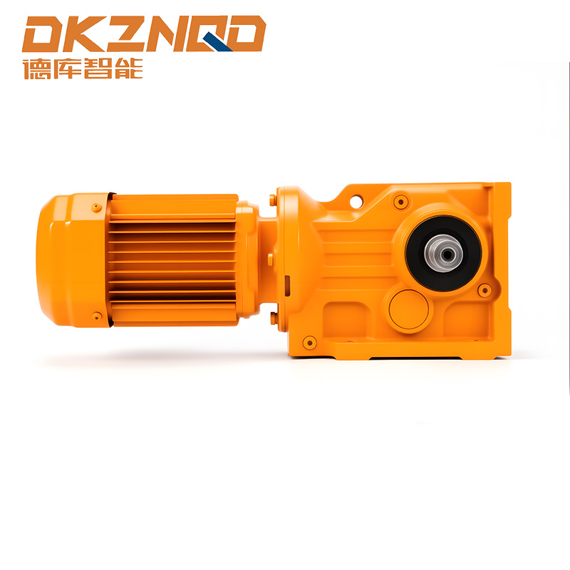 K Series Helical Bevel Gearmotor with Precisely Finished TeethSpiral bevel gear sets require precise tooth surface finishing and modification; this K Series gearmotor is built with such machining, ensuring a contact pattern that holds under full load, suitable for right-angle high-torque applications.View Product →
For procurement, tooth finishing quality is a visible sign of how much effort the factory puts into its gears. Ask for a contact pattern test report and a gear accuracy grade. If they cannot supply one, consider the risk carefully.
How Tooth Profile Affects Reducer Selection
The best reducer choice depends on the tooth profile type that matches your application. Helical gear reducers, for example, have teeth with an inclined contact line. This gives them higher load capacity and lower noise compared with straight spur gears. They are common for conveyors, mixers, and other equipment where continuous operation matters.
Bevel gear reducers use conical gear pairs to change the direction of rotation by 90 degrees. Depending on the tooth profile, they can be straight-bevel, spiral-bevel, or hypoid. Spiral bevel gears have curved teeth that engage more gradually, making them quieter and more reliable at higher speeds. The K Series is a good example because it combines bevel gears with a helical output stage.
Worm gear reducers, on the other hand, have a tooth profile that is not involute. The worm thread resembles a screw, and the gear tooth is shaped to match that screw. The sliding contact between the worm and the gear means that tooth profile, material pairing, and lubricant are much more critical than in an involute pair. If the profile is not manufactured accurately, the worm drive will heat up quickly and lose efficiency.
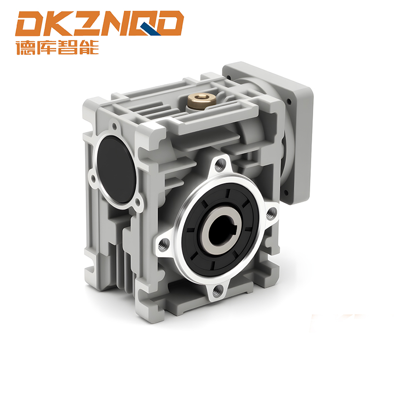 RV Worm Gear Reducer with Hardened Worm and Bronze GearThis worm gear reducer features a surface-hardened alloy worm (56-62 HRC) and wear-resistant tin bronze gear, with self-locking single-stage ratios, providing compact and reliable speed reduction for sliding-contact applications.View Product →
When you select a reducer, first decide what tooth profile behavior your equipment demands. High shock loads point to hardened helical gearing. Right-angle installation with high torque points to a bevel or hypoid design. Compact self-locking applications might use a worm drive. Then verify that the manufacturer applies proper tooth modifications for that specific profile.
Quality Checks and Common Procurement Pitfalls
The last step is to protect your purchase with concrete quality checks. A brochure with a large torque table is not enough. Request the following information before you place an order.
- Gear accuracy grade according to ISO 1328 or an equivalent standard.
- Material and heat treatment report, including surface hardness and case depth.
- Tooth profile deviation measurement data from a gear measuring machine.
- Contact pattern test after the gearbox is assembled.
One common pitfall is assuming that all 20-degree pressure angle gears are interchangeable. They are not. The actual profile must match the mating gear, and deviations in profile shift or tooth thickness can cause interference. Another pitfall is ignoring gear accuracy. A gearbox with a lower accuracy grade, such as 9 instead of 6, will generate more noise and run hotter, even if the material is the same. For critical equipment, insist on a measured gear accuracy confirmation before delivery.
It is always helpful to work with a manufacturer that can show you its testing center and explain the tooth profile parameters of each standard model. The company behind this article, Deku Intelligent Drive, has more than 21 years of experience manufacturing hard-faced gear reducers, and every production line is backed by real gear metrology and loading tests. That kind of practical background makes a difference when your production depends on reliable motion.
Accurate gear tooth profile is the difference between a quiet, long-lived drive and an early field failure. Ask your supplier hard questions about module, pressure angle, profile shift, and tooth modifications. The answers you receive will tell you more than any torque table.
 05 Jun,2025