

 ENG
 English
 русский
 Español
 Türk

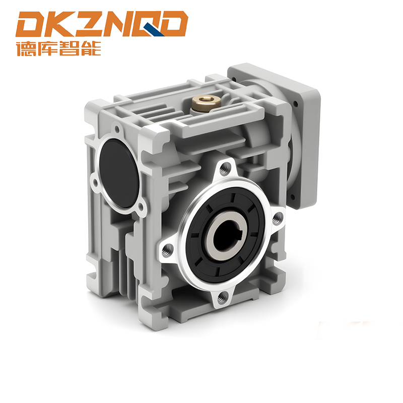
Imagine you are setting up a belt conveyor that must carry 500 kg of material at a slow, steady speed. Before you choose a gearmotor or a reducer, the first number you need is torque — not the horsepower rating, not the input speed. In real drive systems, torque determines whether the shaft can move the load at all. This guide explains how gear torque works, how gear ratio and efficiency change it, and how a manufacturer approaches torque-based selection for industrial gear reducers.
What Is Gear Torque and Why Does It Matter?
Torque is the rotational force produced on a shaft. It is measured in Newton-meters (N·m) and calculated from the tangential force multiplied by the radius of the object being driven. In a gear reducer, the input torque from the motor is transformed as the gear train changes speed. Reducing the output speed almost always increases torque at the output shaft, while increasing speed reduces it.
Plainly: gears do not create energy. They trade speed for torque. If a gearbox multiplies speed, the torque drops by the same proportion (ignoring losses). If it reduces speed, torque is amplified. That is why the gear ratio is the central parameter in torque calculations.
The Gear Ratio and Torque Relationship
Gear ratio is defined as the number of teeth on the driven gear divided by the number of teeth on the driving gear. It is also equal to the input speed divided by the output speed in the same stage. A 24:1 ratio means that when the input shaft turns 24 times, the output shaft turns once.
With any pair of gears, power (P) remains constant in ideal conditions: P = T × ω. Since angular speed ω decreases with a larger ratio, torque T must increase. The practical formula for the output torque is:
where i is the total gear ratio and η is the overall mechanical efficiency of the reducer.
Example: A 1450 rpm motor drives an R Series helical geared motor with a 24.17:1 ratio. Output speed is about 60 rpm. If the load needs 460 N·m at the output, the input side must deliver roughly 20 N·m when efficiency is taken as 0.95. An engineer can use this result to select the motor rating and the reducer frame size.
How Efficiency Changes Real Output Torque
Efficiency is the fraction of input power that reaches the output shaft. The rest is lost as friction, heat, windage, and lubricant churn. For industrial gear reducers, typical efficiency values are roughly:
- Helical parallel shaft and helical bevel reducers: 94–98%
- Hypoid gear reducers: 90–95%
- Worm gear reducers: 40–85%, with self-locking types on the lower end
| Reducer Type | Typical Efficiency | Torque Characteristic | Best Fit Application |
|---|---|---|---|
| Helical | 94–98% | High torque, low backlash | Continuous duty with moderate shock |
| Helical-Bevel | 94–97% | High torque in right-angle layout | Space-limited installations |
| Worm | 40–85% | High reduction ratio, self-locking | Lifting and emergency hold |
| Hypoid | 90–95% | Quiet, high torque, low backlash | Precision positioning |
These numbers are not just estimates. They change the required motor power. A worm gearbox with 70% efficiency needs 30% more input torque than a helical gearbox with 97% efficiency to produce the same output torque. In continuous-duty machinery, that difference affects energy cost, heat generation, and service life.
Worm gear reducers are a different case. Their high speed reduction and self-locking nature can be an advantage for lifting equipment, but the efficiency drops sharply at high ratios. To keep a worm reducer healthy for years, pay attention to operating temperature and lubrication. Maintenance of an RV worm gear reducer directly affects torque stability.
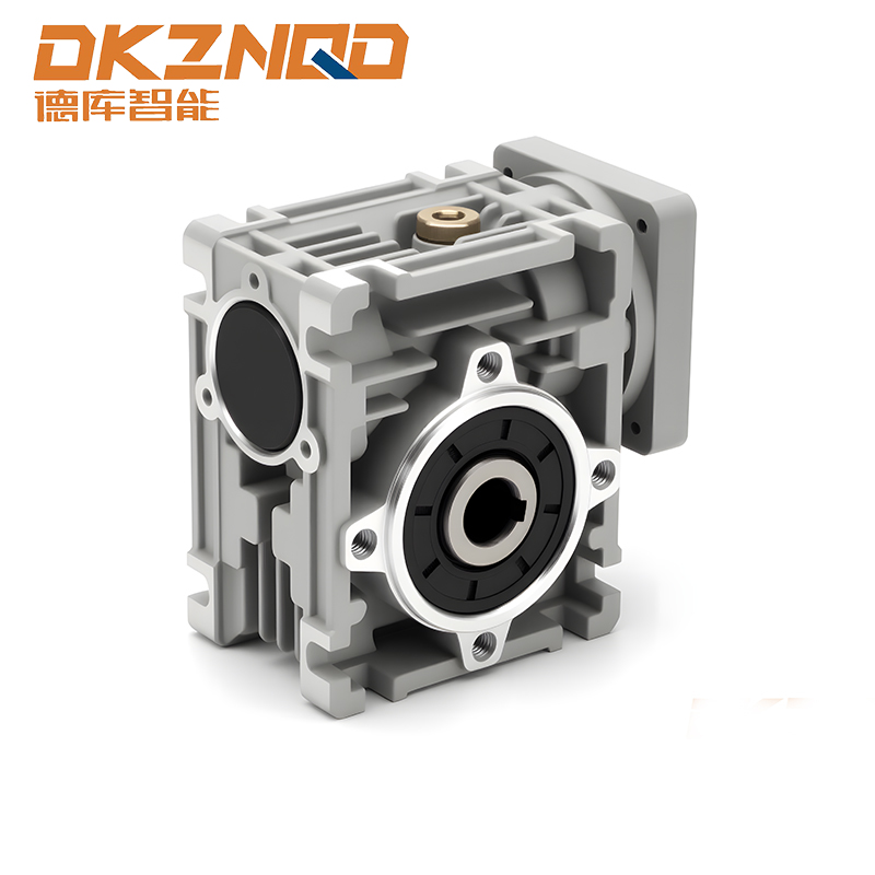 RV Worm Gear Reducer with Self-Locking Feature and High Torque CapacityThis RV reducer offers a power range of 0.06–15 kW and maximum output torque of 1300 Nm, with a double configuration for ratios up to 5000. Its self-locking single-stage design suits lifting equipment, but note that high ratios reduce efficiency, so maintain proper lubrication and temperature for stable torque.View Product →
Common causes of unexpected torque loss are poor lubrication, tooth profile mismatch, misalignment, oversized bearings, and excessive backlash. When you compare reducers from different suppliers, always ask about tested efficiency at the rated torque, not only the theoretical ratio.
How to Calculate Required Torque for Your Application
Application torque is not a single number. You need both continuous torque and peak torque. Continuous torque is the steady load while running. Peak torque occurs during startup, acceleration, shock loads, or reversing. In many conveyors and mixers, peak torque can be 1.5 to 2 times the running load.
One practical way to define the required torque is to start from the driven machine. For a winch or hoist, take the load force multiplied by the drum radius. For a conveyor, compute the belt tension using friction coefficient and load mass, then convert this force into required torque at the drive pulley.
Once you have the peak torque value, multiply it by a service factor (SF). Many industrial reducer catalogs recommend SF of 1.3 for uniform loads, 1.5 for moderate shocks, and 1.8 or more for heavy shock applications. The reducer's rated output torque must be equal to or greater than peak torque × SF.
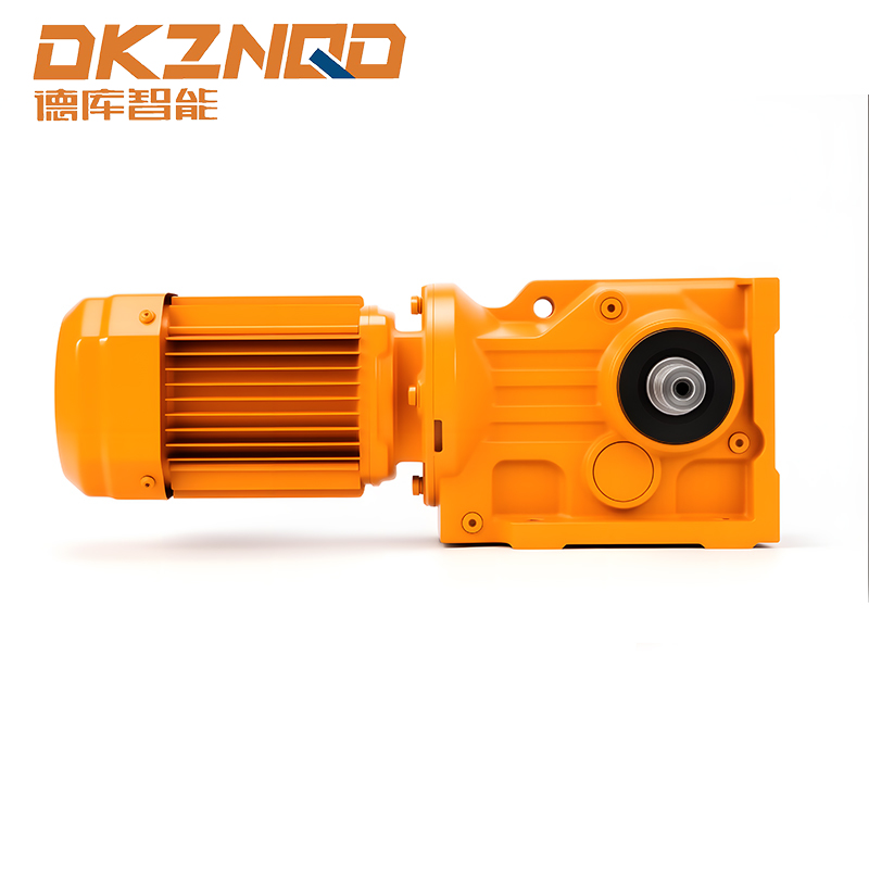 K Series Helical Bevel Gearmotor for Right-Angle Torque TransmissionWith power up to 200 kW and torque up to 50,000 Nm, this right-angle gearmotor delivers high torque density in compact spaces. Ideal for applications where space is limited and torque demands are high, it ensures stable efficiency and low noise.View Product →
Right-angle applications often combine space constraints with high torque demand. K Series helical bevel gearmotors handle this by transmitting power through a spiral bevel stage, giving a compact right-angle solution with high torque density and stable efficiency.
Measuring and Verifying Torque in Gear Reducers
On a test bench, torque is measured in one of two ways. Torque sensors placed between the motor and the output shaft measure the actual twisting load. The loss method measures input power and output power separately; the difference is the torque loss. The second method is a fast check for factory acceptance, but the load condition on a real machine is often more important than the laboratory number.
Before accepting a reducer, ask how the quoted output torque was obtained. Was it based on theoretical calculations or verified under rated conditions? Ask for a torque chart across the speed range, not only at one point.
Practical Selection Tips for Gear Reducers
Choosing a reducer for torque and belt drive is straightforward when the numbers are clear.
- Confirm the required output speed and output torque from the machine.
- Select the gear ratio that brings the motor speed close to the required output speed.
- Choose the reducer series based on the installation orientation: helical for inline, helical-bevel for right angle, hypoid for quiet compact drive, worm for low-speed torque with emergency braking.
- Compare efficiency at the operating point, not just at full load.
- Check thermal capacity. A gearbox that is correctly sized by torque may still overheat if the application has long cycles at low speed.
- Do not forget the motor. The gearbox input is the motor's output. If the motor delivers more starting torque than the reducer's input rating, the first teeth can fail.
For high starting torque and shock loads on a conveyor, R Series helical geared motors offer a balanced design with excellent torque quality and smooth running in a compact housing.
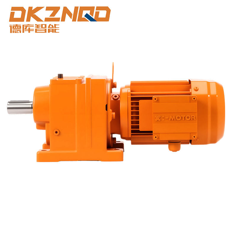 R Series Helical Gearmotor for Reliable and Efficient Torque TransmissionThis versatile helical gearmotor covers power from 0.12 to 160 kW with torque up to 18,000 Nm, offering high efficiency and load capacity. Suitable for uniform loads and moderate speed reduction, it provides a dependable choice for long-term operation.View Product →
R Series parallel shaft helical gearmotors are a solid starting point when the load is uniform, the speed reduction is moderate, and long-term efficiency is the priority.
Frequently Asked Questions about Gear Torque
Q1: What is the difference between torque and horsepower?
Torque measures the rotating force. Horsepower measures the rate at which work is done. A low-torque, high-speed motor can produce the same power as a high-torque, low-speed motor, but the mechanical output speed and force are different.
Q2: Does a higher gear ratio always mean more torque?
Yes within practical limits. A higher ratio raises output torque, but it also reduces speed and lowers efficiency, so the actual torque gain is less than the ratio suggests.
Q3: How do I choose a gear reducer based on torque?
Calculate the continuous and peak torque at the output shaft, apply a service factor and compare it with the reducer's torque rating. Make sure the rating is at the actual output speed and that the thermal rating is not exceeded.
Q4: Can a gear reducer be damaged when torque exceeds its rated torque?
Overload torque causes tooth root bending stress and contact stress to rise quickly. Repeated overloads can lead to pitting, cracks, and eventually failure. A safety margin of 1.3 to 2.0 is a common industry practice.
Gear torque is not a single static number. It is the product of motor torque, speed ratio, efficiency, and the real load pattern. The right way to specify a reducer is to calculate peak torque with a service factor, compare it with the mechanical rating of the gearbox, and confirm the efficiency at the working speed. That process takes minutes on paper but prevents expensive field failures when the machine is running.
 05 Jun,2025