

 ENG
ENG
 English
 русский
 Español
 Türk
Türk

Why Hazardous Location Classifications Define Motor Selection
Every rotating machine installed in a chemical plant, refinery, grain terminal, or paint booth operates under a risk profile that has nothing to do with horsepower or speed. The deciding factor is whether flammable gas, vapor, or combustible dust is present in the surrounding air, and how often. Classification systems exist to translate that risk into a language that engineers, inspectors, and equipment manufacturers can all read the same way, which is why an explosion proof motor is never selected on catalog specifications alone.
In North America, the National Electrical Code splits hazardous areas into Class I, II, and III, then further divides each class into Division 1 or Division 2 depending on whether the hazardous material is present continuously or only during abnormal conditions. The IEC and ATEX framework used across most other regions instead uses Zones 0, 1, and 2 for gas, and Zones 20, 21, and 22 for dust. Both systems describe the same underlying question: how likely is an ignitable mixture to be present at the moment a spark or hot surface could occur.
| Classification System | Continuous Hazard | Intermittent Hazard | Abnormal Condition Only |
|---|---|---|---|
| NEC Class I | Division 1 | Division 1 | Division 2 |
| IEC and ATEX Zones | Zone 0 | Zone 1 | Zone 2 |
| Dust Equivalent | Zone 20 | Zone 21 | Zone 22 |
A hazardous location motor purchased for a Division 2 pump room will almost never satisfy the requirements of a Division 1 mixing vessel, even though both rooms might handle the same solvent. The distinction matters because Division 1 equipment must prevent an internal ignition from reaching the outside atmosphere at all, while Division 2 equipment is built on the assumption that an ignitable mixture is rarely present, so the design margin can be smaller.
What Makes a Motor Explosion Proof
The term explosion proof is frequently misunderstood outside of engineering circles. It does not mean the motor cannot be damaged by an explosion. It means that if an internal spark ignites gas that has entered the enclosure, the resulting flame and pressure are contained inside the housing long enough to cool below the ignition temperature of the surrounding atmosphere before any gas escapes. This is achieved through a flame path, a carefully machined joint between the motor frame and end bells that is narrow and long enough to quench a flame front.
Three broad protection concepts appear repeatedly across hazardous location motor catalogs, and each solves the ignition problem in a different way.
- Flameproof enclosure, often marked Ex d, contains an internal explosion rather than preventing one.
- Increased safety, marked Ex e, eliminates sparking parts and controls surface temperature so ignition cannot start in the first place.
- Non-sparking or restricted breathing designs, marked Ex n, are intended for Zone 2 areas where ignitable mixtures are unlikely.
The chart below compares a relative protection index across four common motor construction types, based on how conservatively each design assumes an ignition source could be present.
Relative Protection Index by Motor Construction Type
None of these designs is universally correct. A Zone 2 packaging line rarely needs the cost and weight of a fully flameproof frame, while a Division 1 solvent recovery unit cannot substitute a lighter increased safety motor no matter how attractive the price difference looks on paper.
How Gearbox Design Integrates with Explosion Proof Motors
A hazardous location motor rarely operates alone. Conveyors, mixers, and agitators typically need torque multiplication and speed reduction, which means the motor is paired with a gearbox that must match both the mechanical duty and the area classification of the driven equipment. Housing material, shaft seal design, and breather placement all have to be coordinated so the combined unit does not introduce a new ignition path that the motor alone would never have created.
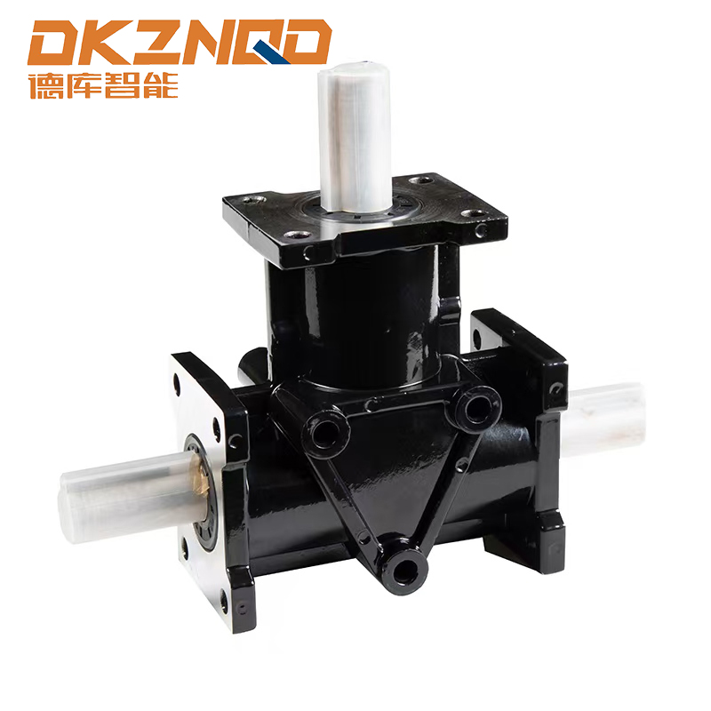
Right angle designs are common in hazardous plants because they allow the motor to be mounted away from splash zones or narrow catwalks. A spiral bevel gearbox is frequently chosen for these right angle drives because the spiral tooth geometry engages more gradually than a straight bevel design, which reduces vibration and the associated risk of loosened fasteners over long duty cycles. Reduced vibration also lowers the chance of seal wear at the output shaft, which is one of the more common points where dust or vapor can migrate toward electrical components if left unmonitored.
Selecting the correct combination is a sequential process rather than a single specification lookup. The flow below outlines the order most engineering teams follow when matching a gearbox to an explosion proof electric motor.
Motor and Gearbox Selection Sequence
Skipping any step in this order tends to surface later as a mismatch between the motor nameplate rating and the gearbox input torque, which usually forces a costly field replacement rather than a simple paperwork correction.
ATEX Certification vs Class I Division 1 Explosion Proof Motors
An ATEX certified gearmotor and a Class I Division 1 explosion proof motor are answering the same fundamental question through two different regulatory frameworks, and the two are not automatically interchangeable on paper even when the underlying engineering is similar. ATEX certification is built around the European directive system and issues a code that identifies equipment group, category, gas or dust protection, temperature class, and equipment protection level. Class I Division 1 certification in North America is handled through nationally recognized testing laboratories and uses a different marking format, though the underlying flame path and temperature testing methods overlap significantly.
Standard Motor vs Explosion Proof Motor Comparison
Outer shape represents explosion proof motors; inner shape represents standard industrial motors, scaled across five relative attributes.
| Attribute | ATEX Certified Gearmotor | Class I Div 1 Explosion Proof |
|---|---|---|
| Governing Body | Notified body under EU directive | Nationally recognized testing lab |
| Marking Style | Group, category, gas group code | Class, division, group letters |
| Temperature Class | T1 through T6 rating | T1 through T6 rating |
| Typical Use Region | Europe, Middle East, parts of Asia | United States, Canada |
Plants that export equipment internationally often specify dual certified motors so a single design can serve both markets without duplicating engineering drawings, which shortens procurement timelines when a facility is standardizing hazardous location motor purchases across multiple sites.
How Investment and Maintenance Costs Compare Across Protection Classes
Budget conversations around explosion proof motor classifications tend to focus only on the purchase price, but the more useful comparison looks at total ownership cost across the equipment life cycle. The column chart below illustrates a relative initial investment index across five protection classes, using Class I Division 2 as the baseline.
Relative Initial Investment Index by Protection Class
Maintenance intervals shift in the opposite direction. Motors and spiral bevel gearboxes built for the strictest zones are engineered with sealed bearings, corrosion resistant coatings, and simplified breather designs that generally extend the time between required inspections, which partially offsets the higher purchase price over a multi year service window.
Average Inspection Interval Trend Over Five Years of Service
Lower line represents explosion proof rated equipment; upper line represents standard industrial motors requiring more frequent inspection as duty cycles accumulate.
Where Industrial Chemical Plant Gearboxes and Motors Are Deployed
Industrial chemical plant gearboxes and hazardous location motors show up in far more places than the tank farm most people picture first. The list below covers the areas where classification mistakes carry the most operational and safety consequence.
- Solvent recovery and distillation skids where vapor concentration fluctuates with batch cycles.
- Pigment and resin mixing rooms where fine combustible dust accumulates on structural surfaces.
- Wastewater treatment digesters that generate methane during anaerobic breakdown.
- Grain handling and milling operations with airborne organic dust.
- Paint spray booths and finishing lines with continuous solvent vapor exposure.
- Oil and gas wellhead pumping units located in remote outdoor Zone 1 or Zone 2 areas.
Each of these environments places different demands on shaft seals, cooling fan design, and cable entry hardware, which is why a hazardous location motor specification sheet for a grain terminal will rarely translate directly to a solvent recovery skid even when the horsepower and frame size look identical on paper.
How to Maintain Flame Proof Industrial Motors in Service
Certification only describes the equipment as it left the factory. Field performance depends heavily on how the flame path joints, cable glands, and gearbox seals are treated during routine service. A flame proof industrial motor that has been reassembled with a damaged or improperly torqued flame path joint no longer meets its original protection rating even if the nameplate still shows the correct classification.
- Inspect flame path surfaces for corrosion, pitting, or paint buildup before every reassembly.
- Torque enclosure fasteners to the value specified by the certification documentation, not a generic shop standard.
- Verify cable gland seals remain intact and that unused conduit entries are properly plugged with rated hardware.
- Check gearbox breather vents and shaft seals for wear, since a failed seal can create an unintended path for vapor ingress.
- Confirm bonding and grounding connections have not loosened from vibration over the operating period.
- Keep a documented record of every disassembly so certification status can be traced during audits.
Facilities that treat these steps as a checklist item rather than a formality tend to see fewer unplanned shutdowns tied to seal bevel gearbox systems failures, since most of the wear points listed above are visible well before they become an actual containment issue.
Frequently Asked Questions
Q1: What is the difference between explosion proof and intrinsically safe equipment?
Explosion proof equipment contains an internal explosion so it cannot ignite the surrounding atmosphere, while intrinsically safe equipment limits electrical energy so a spark is never powerful enough to cause ignition in the first place. The two approaches solve the same problem through different design philosophies and are rarely interchangeable in the same application.
Q2: Can a Division 2 rated motor be installed in a Division 1 location?
No. Division 1 locations assume an ignitable mixture is present continuously or frequently, and only equipment tested and marked for Division 1 service provides the containment margin required. Installing lower rated equipment in a more hazardous area is a common and serious code violation.
Q3: How often should explosion proof motors be inspected?
Inspection frequency depends on duty cycle, ambient conditions, and local regulatory requirements, but most facilities schedule flame path and seal checks on an annual basis at minimum, with more frequent checks for equipment running in continuous vapor exposure.
Q4: Does a gearbox need its own explosion proof rating?
The gearbox itself does not generate electrical sparks the way a motor does, but its housing, seals, and any integrated sensors must still be compatible with the area classification so it does not compromise the overall assembly rating when coupled to the motor.
Q5: What does the temperature class marking on a motor nameplate mean?
The temperature class, shown as T1 through T6, indicates the maximum surface temperature the equipment can reach under normal and fault conditions, ensuring that surface stays below the autoignition temperature of the gases expected in that area.
Q6: Are ATEX certified gearmotors accepted in North American facilities?
Generally not without additional certification, since ATEX and North American testing bodies use different standards and marking systems. Multinational operators often specify dual certified equipment to avoid maintaining separate designs for each region.
 05 Jun,2025