

 ENG
ENG
 English
 русский
 Español
 Türk
Türk

Why Materials Handling Systems Fail at the Gearbox, Not the Motor
When a conveyor line stalls or a bucket elevator drive locks up, operators usually check the motor first. In practice, the drivetrain component that fails earliest is almost always the gearbox interface, not the motor windings. Repeated shock loads, shaft misalignment, and vibration fatigue concentrate stress at the reduction unit, particularly where the gearbox connects directly to a rotating shaft rather than through a coupling.
This is the reason shaft mount speed reducers exist as a distinct product category. Instead of bolting a gearbox to a bedplate and connecting it through flexible couplings, a shaft mount design hangs the reducer directly on the driven shaft, using a hollow bore and a stabilizing arm to resist rotation. The approach removes alignment variables but introduces different engineering demands around bearing life, backlash control, and mounting rigidity.
Understanding those demands before specifying a reducer prevents a common and costly mistake: selecting a unit based on horsepower rating alone while ignoring shock load class, ambient conditions, and mounting geometry.
What Makes Shaft Mount Speed Reducers Different From Inline Gearboxes
A conventional inline or parallel shaft reducer sits on its own foundation and transmits torque through a coupling to the driven equipment shaft. A shaft mount unit instead uses a hollow output bore that slides directly over the driven shaft, secured with a locking device such as a taper bushing or keyed collar. Torque reaction is absorbed by an external arm rather than by foundation bolts alone.
- No separate output shaft alignment is required, since the bore rides on the driven shaft itself
- Installation footprint is smaller, which matters on retrofit conveyor lines with limited clearance
- Vibration transmission path changes, so bearing selection and lubrication intervals differ from inline units
- A torque arm or slide base becomes a required accessory rather than an option
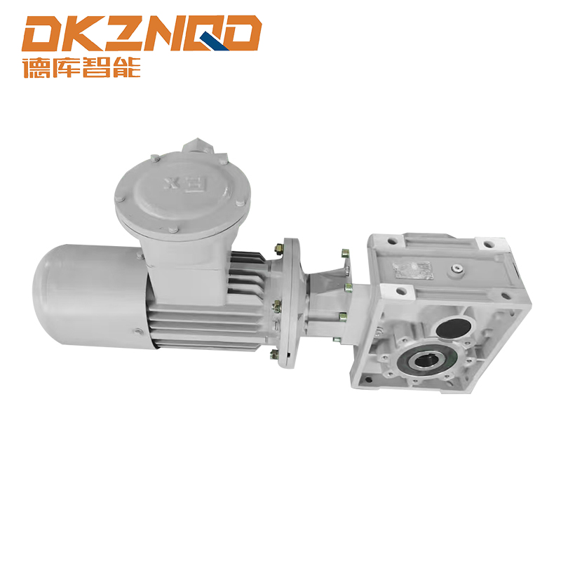
Two design families dominate this category: helical or helical-bevel shaft mount units for general duty, and hypoid gear designs for applications needing higher reduction ratios in a compact housing. A BKM Hypoid Gear Reducer falls into the second family, using a hypoid gear set to achieve a right-angle or high-ratio reduction while keeping the housing profile low relative to the torque it transmits.
How Hypoid Gear Geometry Improves Torque Density
Hypoid gearing offsets the pinion axis below the centerline of the gear, which allows more tooth contact area than a straight bevel arrangement of the same size. That extra contact area is what gives a hypoid design its torque density advantage: a smaller housing can carry a higher load rating than an equivalent straight bevel or worm unit.
For conveyor and bulk handling applications, this matters in two practical ways. First, a compact housing reduces the overhung load on the driven shaft, which extends bearing life. Second, the offset geometry allows smoother engagement under shock loading, which is common in crusher feed conveyors, bucket elevators, and agitator drives where load spikes occur unpredictably.
Dodge Shaft Mount Reducers vs BMR Shaft Mount Speed Reducers: Selection Criteria
Two commonly referenced design lineages in the shaft mount category are heavier-duty units built for continuous three-shift operation, and lighter general purpose units built for intermittent duty. Rather than comparing brand names, it is more useful to compare them by the engineering attributes that separate one duty class from another, since dodge shaft mount reducers and bmr shaft mount speed reducers are frequently used as generic category terms in procurement documents.
| Attribute | Heavy Duty Class | General Purpose Class |
|---|---|---|
| Typical bearing life target | 60,000 to 100,000 hours L10 | 20,000 to 40,000 hours L10 |
| Shock load tolerance | High, rated for repeated peak loads | Moderate, uniform load preferred |
| Housing material | Cast iron, ribbed for rigidity | Cast iron or aluminum alloy |
| Typical duty cycle | Continuous, 24 hour operation | Intermittent, single or double shift |
| Common application | Crusher feeders, bucket elevators, mixers | Package conveyors, light material transfer |
Matching the duty class to the actual operating profile, rather than defaulting to the largest available frame size, is what keeps lifecycle cost under control. Oversizing adds unnecessary capital cost, while undersizing shortens bearing life dramatically because bearing fatigue life scales steeply with load.
The Role of a Torque Arm for Gearbox Stability
Because a shaft mount reducer has no independent foundation, it relies on a reaction member to prevent the housing from rotating with the shaft. This member is the torque arm, and its design directly affects gear alignment, bearing loading, and long-term noise levels.
Rigid Torque Arm
A solid link between the reducer housing and a fixed structural point. This is the most common configuration for medium duty conveyor drives, since it is simple to install and inspect.
Slide Base Torque Arm
Mounts the reducer on a base plate that allows small linear adjustment, useful when belt tensioning or chain adjustment requires the reducer position to shift slightly over time.
Spring Cushioned Torque Arm
Introduces a damping element between the arm and the mounting structure, absorbing shock spikes before they transmit into the gear housing. This option is worth the added cost on applications with frequent start stop cycling or pulsating loads.
A torque arm that is undersized or mounted at an incorrect angle is one of the most common causes of premature bearing failure in shaft mounted gearboxes, because it allows micro movement that gradually loosens the shaft connection.
Hollow Shaft Gear Reducers in Conveyor Gearbox Reducer Applications
Hollow shaft designs are the mechanical foundation of the shaft mount category. The bore size, locking method, and shaft fit tolerance all affect how reliably the reducer transmits torque without slipping or fretting.
| Locking Method | Best Suited For | Maintenance Note |
|---|---|---|
| Taper bushing | Frequent removal and reinstallation | Requires periodic bolt torque check |
| Keyed shaft with setscrew | Lower cost, moderate load | Watch for keyway wear over time |
| Shrink disc | High torque, minimal backlash tolerance | Installation requires precise torque sequencing |
In a typical conveyor gearbox reducer installation, the hollow shaft slides directly onto the head shaft or tail shaft of the conveyor, eliminating the coupling and its associated alignment work. This reduces installation time significantly compared to a foot mounted reducer plus coupling arrangement, and it removes one common point of misalignment related downtime.
Shaft Mounted Reducer in Agriculture Industry Equipment
Agricultural drive applications present a different challenge set than industrial conveyor lines. Dust ingress, wide temperature swings, and seasonal storage between duty periods all affect reducer selection.
- Sealing quality matters more than raw torque rating, since grain dust and moisture are common failure contributors
- Units that sit idle for months between harvest seasons benefit from corrosion resistant coatings on external hardware
- Shock loading from uneven field terrain on mobile equipment favors a cushioned torque arm over a rigid link
- Field serviceability is a practical requirement, since a farm operation may not have access to a machine shop for emergency repair
A shaft mounted reducer in agriculture industry use is often specified with a higher service factor than the same horsepower application would receive in a controlled indoor facility, precisely because environmental variability adds unpredictable load spikes that a clean industrial environment does not produce.
Sizing Heavy Duty Drive Systems: A Practical Checklist
Correct sizing of shaft mounted gearboxes depends on more than nameplate horsepower. The following checklist reflects the variables that most frequently get overlooked during specification.
- Confirm actual peak torque, not average running torque, including startup inertia
- Identify shock load classification based on driven equipment type
- Verify shaft diameter and keyway dimensions against the reducer bore tolerance
- Select torque arm style based on available mounting structure and vibration profile
- Check ambient temperature range against lubricant viscosity rating
- Confirm mounting orientation, since some hollow shaft designs have position dependent lubrication paths
- Review service factor against duty cycle hours per day, not just per week
Skipping the shock load classification step is the single most common sizing error, because two applications with identical average horsepower can have very different peak torque profiles depending on whether the driven load starts under full material load or empty.
Maintenance and Failure Prevention for Shaft Mounted Gearboxes
Because shaft mount units share their bore directly with the driven shaft, maintenance routines differ slightly from foot mounted gearboxes. The table below summarizes common failure indicators and their likely root cause.
| Symptom | Likely Cause | Recommended Action |
|---|---|---|
| Unusual noise at low load | Backlash increase from gear wear | Inspect gear mesh, check lubricant condition |
| Heat buildup at housing | Incorrect lubricant viscosity or level | Verify oil grade against ambient temperature |
| Loosening on driven shaft | Torque arm misalignment or worn bushing | Recheck torque arm angle and bolt torque |
| Vibration at coupling point | Shaft fit tolerance mismatch | Confirm shaft diameter within specified tolerance range |
A structured inspection interval, typically every 500 operating hours for continuous duty applications, catches most of these issues before they progress to bearing failure. Oil analysis, rather than a fixed calendar based oil change, gives a more accurate picture of remaining lubricant life in variable temperature environments common to heavy duty drive systems.
Frequently Asked Questions
Q1: What is the main advantage of a shaft mount speed reducer over a foot mounted gearbox?
A shaft mount unit eliminates the coupling and its alignment requirement by mounting directly on the driven shaft, which reduces installation time and removes a common source of misalignment related failure.
Q2: How do I know if I need a torque arm for gearbox stability or a rigid mount?
If the application has consistent, steady loading and a solid mounting structure nearby, a rigid torque arm is usually sufficient. If the load pulses or the equipment vibrates significantly, a spring cushioned torque arm reduces stress on the gear housing.
Q3: Why choose a hypoid gear reducer instead of a helical shaft mount unit?
Hypoid gearing offers higher torque density in a more compact housing, which is useful where space is limited or where a right angle output orientation is required, such as many bucket elevator and mixer drive layouts.
Q4: How often should hollow shaft gear reducers be inspected?
Continuous duty applications typically warrant inspection every 500 operating hours, with attention to lubricant condition, torque arm alignment, and any change in operating noise or vibration.
Q5: Are shaft mounted gearboxes suitable for agricultural equipment that sits idle for months?
Yes, provided the unit has adequate sealing against dust and moisture and external hardware is corrosion resistant. Long idle periods make seal quality more important than raw torque rating in most field equipment applications.
 05 Jun,2025