ENG
ENG
 English
 русский
 Español
 Türk
Türk
1. How to adjust the meshing clearance of the worm gear pair of the S series helical gear worm gear motor?
(1) Analysis of the impact of meshing clearance on transmission accuracy and life
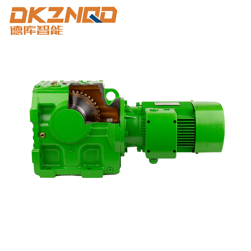
In the S series helical gear worm gear motor, the meshing clearance of the worm gear pair is a key parameter, which has a significant impact on the transmission accuracy and service life of the equipment.
From the perspective of transmission accuracy, excessive meshing clearance will cause serious problems. In precision transmission systems, such as the feed shaft drive of CNC machine tools, excessive clearance will cause the worm gear to be unable to follow the worm gear movement in a timely and accurate manner during the operation of the motor output shaft, resulting in obvious lag. This will cause deviations in the positioning of the workbench, and it will not be able to achieve the high-precision position required by the design, which will greatly affect the processing accuracy. For example, when processing precision molds, positioning deviations may cause errors in the key dimensions of the mold, resulting in the scrapping of the mold.
As for the service life, unreasonable meshing clearance is also very harmful. When the clearance is too large, the impact force between the tooth surfaces of the worm gear will increase significantly during the meshing process. Each time the meshing occurs, the collision of the tooth surface is like a small hammer hitting the tooth surface. If this continues for a long time, fatigue wear will occur on the tooth surface, resulting in pitting, peeling and other damage. The increased wear will gradually destroy the tooth shape, further increase the meshing clearance, form a vicious cycle, and eventually lead to premature failure of the worm gear, greatly shortening the service life of the equipment.
(2) Introduction of adjustment methods (such as shim adjustment, axial fine-tuning, etc.)
Shim adjustment is a relatively common method. In the installation structure of the worm gear, a shim group is usually set between the bearing seat of the worm and the housing. When the meshing clearance needs to be adjusted, the axial position of the worm is changed by increasing or decreasing the number or thickness of shims. If the clearance is too large, increase the thickness of the shim to move the worm away from the worm wheel, thereby reducing the clearance; conversely, if the clearance is too small, reduce the thickness of the shim to move the worm closer to the worm wheel. This method is relatively simple to operate and has a low cost, but the adjustment accuracy is limited and it is not easy to change again after adjustment.
Axial fine-tuning uses some specially designed mechanisms to achieve axial micro-movement of the worm. For example, a threaded adjustment device is installed at one end of the worm, and the worm is pushed to move axially by rotating the adjustment nut. This method can achieve relatively precise clearance adjustment and is suitable for occasions with high transmission accuracy requirements. There are also hydraulic or pneumatic devices to achieve axial fine-tuning, and the movement of the worm can be accurately controlled by controlling the pressure to further improve the adjustment accuracy.
(3) Provide industry standards or internal control indicators of enterprises
In terms of industry standards, for S series helical gear worm reducer motors for general industrial applications, the meshing clearance of the worm pair is usually required to be controlled between 0.05 and 0.2mm. This range can not only ensure a certain transmission accuracy, but also avoid problems such as heating and seizure caused by too small a clearance. For example, in general equipment in the machinery manufacturing industry, if S series reducer motors are used, most companies will follow this industry standard for assembly and inspection.
Some companies that have higher requirements for product quality and performance will formulate more stringent internal control indicators. For example, in high-end automation equipment manufacturing companies, their internal control indicators may control the meshing clearance between 0.03 and 0.1 mm. In order to achieve this indicator, the company will use more precise processing technology in the production process, such as high-precision grinding, to ensure the tooth profile accuracy of the worm gear; in the assembly process, more advanced measuring instruments and assembly technologies, such as laser measuring instruments, will be used to accurately measure the clearance to ensure the reliability and stability of the product under high-load and high-precision operating environments.
2. What measures have been taken to control the noise of the S series helical gear worm reducer motor?
(1) Discuss the main noise sources (gear meshing, bearing vibration, etc.)
During the operation of the S series helical gear worm reducer motor, the noise sources are relatively complex, among which gear meshing and bearing vibration are the two main noise sources.
Gear meshing noise is caused by the friction, collision and meshing impact between the tooth surfaces when the helical gear and the worm gear mesh with each other. When gears mesh at high speed, the microscopic roughness of the tooth surface will cause impact force at the moment of contact. This impact force will cause vibration of the gear and spread through the air to form noise. At the same time, due to the unreasonable design of the gear modulus, pressure angle and other parameters, or the low processing accuracy, the tooth profile error is large, and there will be instantaneous meshing and meshing impact during the meshing process, further aggravating the generation of noise.
Bearing vibration is also a noise source that cannot be ignored. When the motor is running, the bearing must not only bear radial and axial loads, but also maintain high-speed rotation. If the manufacturing accuracy of the bearing is not high, such as the roundness error of the raceway and the diameter deviation of the rolling element, it will cause unbalanced centrifugal force during the operation of the bearing, causing vibration and noise. In addition, poor lubrication of the bearing will also increase the friction between the rolling element and the raceway, generating additional noise. When the bearing is used for a long time, it will be damaged by wear, fatigue peeling and other damages, and its vibration and noise will be more obvious.
(2) List the noise reduction processes (such as tooth profile trimming, high-precision machining, vibration reduction design, etc.)
Tooth profile trimming is an effective noise reduction process. By properly grinding the top and root of the gear, the shape of the tooth profile is changed, so that the gear can achieve a smoother transition during the meshing process and reduce the impact of meshing in and out. Specifically, a certain thickness is removed from the top of the tooth so that the top of the tooth can gradually contact the tooth surface of the other gear when entering the meshing to avoid sudden impact; the root of the tooth is also ground so that the root of the tooth can be more stable when disengaging. This process can significantly reduce the gear meshing noise.
High-precision processing is the key to ensuring the quality of gears and bearings and thus reducing noise. In terms of gear processing, advanced CNC processing equipment and precision grinding technology are used to strictly control various precision indicators of gears, such as pitch deviation, tooth profile error, tooth direction error, etc., so that the tooth surface of the gear is smoother and the meshing is more accurate, effectively reducing the noise caused by processing errors. For bearings, by improving manufacturing accuracy, ensuring the dimensional accuracy and shape accuracy of the raceway and rolling element, the vibration and noise of the bearing during operation are reduced.
Vibration reduction design is also an important means of noise reduction. In the structural design of the motor, reasonable vibration reduction measures are adopted. For example, elastic vibration damping pads are set between the motor housing and the internal key components, and the rigid connection in the vibration transmission path is changed to an elastic connection, which effectively absorbs and attenuates the vibration energy and reduces the transmission of vibration to the outside. In the design of the box, the number and layout of the reinforcing ribs are increased to improve the rigidity of the box, reduce the box resonance caused by vibration, and thus reduce noise radiation.
(3) Comparison of noise test data before and after optimization
In a real case, a noise test was conducted on an S series helical gear worm reducer motor that had not been optimized for noise reduction. Under rated speed and load conditions, a professional noise test instrument was used to measure at a distance of 1 meter from the motor, and the measured noise value was 85dB (A). This noise level is unacceptable in some places with high requirements for working environment noise, such as precision electronic equipment production workshops and medical equipment manufacturing workshops.
After a series of noise reduction measures were optimized, the noise test was conducted again. The gears were processed by tooth profile trimming technology, and the gears and bearings were processed with high precision. At the same time, a vibration reduction design was added to the motor structure. Under the same test conditions, the measured noise value was reduced to 70dB (A). By comparison, it can be clearly seen that the noise of the optimized motor has been significantly reduced, with a reduction of 15dB (A). This result shows that the comprehensive use of multiple noise reduction processes can effectively improve the acoustic performance of the S series helical gear worm reducer motor and meet the low noise requirements of different application scenarios.
3. How to improve the transmission efficiency of the S series helical gear worm reducer motor?
(1) Analysis of key factors affecting efficiency (friction loss, lubrication method, etc.)
In the S series helical gear worm reducer motor, the improvement of transmission efficiency is affected by many key factors, among which friction loss and lubrication method occupy an important position.
Friction loss is one of the main reasons for the reduction of transmission efficiency. During the meshing process of the helical gear and the worm gear, there is relative sliding between the tooth surfaces, which inevitably generates friction. When the motor is running, this friction consumes a large amount of input energy, converts it into heat energy and dissipates it, thereby reducing the effective output power. For example, due to the high roughness of the tooth surface, the microscopic unevenness will increase the friction between the tooth surfaces, resulting in more energy loss in the friction process. At the same time, unreasonable design of parameters such as the helix angle and module of the worm gear will also increase the sliding friction between the tooth surfaces, further reducing the transmission efficiency.
The influence of lubrication method on transmission efficiency is also very significant. Good lubrication can form an oil film between the tooth surfaces, separate the metal surfaces in direct contact, reduce the friction coefficient, and reduce friction loss. If the lubrication is insufficient, the metal direct contact area between the tooth surfaces will increase, and the friction will increase, which will not only lead to a decrease in transmission efficiency, but also accelerate the wear of the tooth surface. Different lubrication methods, such as splash lubrication and forced lubrication, have different lubrication effects. Splash lubrication is to splash lubricating oil onto the tooth surface through the rotation of the gear. This method is suitable for low speed and light load occasions, but it may not be able to ensure sufficient lubrication at high speed and heavy load. Forced lubrication is to spray lubricating oil onto the meshing point of the tooth surface at a certain pressure through an oil pump, which can provide more reliable lubrication, but the system is relatively complex and the cost is high.
(2) Propose improvement plans (such as selecting low-friction materials, optimizing the lubrication system, etc.)
The selection of low-friction materials is one of the effective ways to improve transmission efficiency. For the manufacture of gears and worm gears, new low-friction coefficient materials can be used, such as high-performance engineering plastics and metal composites. This material has both the strength and wear resistance of metals and the low friction characteristics of engineering plastics, which can significantly reduce the friction loss between tooth surfaces. In the manufacture of worm gears, the use of copper alloy and polytetrafluoroethylene composite materials can effectively reduce friction and improve transmission efficiency compared to traditional bronze worm gears.
Optimizing the lubrication system is also key. For high-speed, heavy-loaded S series reduction motors, a combination of forced lubrication and circulating cooling can be used. The lubricating oil is delivered to the meshing parts of the gears and worm gears at a suitable pressure and flow rate through an oil pump to ensure that a good oil film can be formed even under high loads. At the same time, a cooling device is set to cool the lubricating oil to prevent the oil film from becoming thinner and the lubrication performance from decreasing due to excessive oil temperature. High-performance additives such as anti-wear additives and friction-reducing additives are added to the lubrication system to further improve the performance of the lubricating oil, reduce the friction coefficient, and improve the transmission efficiency.
 05 Jun,2025