ENG
ENG
 English
 русский
 Español
 Türk
Türk
An electric motor nameplate serves as the definitive technical passport for industrial rotating machinery. It contains critical performance metrics, electrical limitations, and mechanical tolerances required for safe installation, operation, and maintenance. Misinterpreting these values can lead to catastrophic equipment failure, severe electrical hazards, and prolonged system downtime. For engineers and technicians managing power transmission setups, understanding these parameters ensures seamless integration with auxiliary components like a high-precision spiral bevel gearbox or heavy-duty variable frequency drives.
This technical guide provides a deep-dive analysis into the standardized nomenclature established by major regulatory bodies, focusing heavily on National Electrical Manufacturers Association standards. By breaking down electrical ratings, thermal insulation properties, and mechanical characteristics, industrial operators can maximize motor longevity and efficiency while optimizing system-wide performance metrics.
Industrial Standards and Governing Frameworks
Industrial electric motors are manufactured and rated under strict regulatory frameworks to guarantee universal compatibility, safety, and performance transparency. The two dominant global standards organizations are the National Electrical Manufacturers Association, widely utilized across North America, and the International Electrotechnical Commission, dominant throughout Europe and Asia.
While both systems achieve the same objective—defining the safe operating envelopes of rotating electrical machines—they employ different structural philosophies, measurement units, and terminal designations. Understanding motor nameplate symbols requires familiarity with the specific framework governing the manufacturing of the machine.
NEMA Standards
NEMA specifications focus heavily on robust designs with standardized frame sizes denoted in imperial units (inches). Performance metrics prioritize high overload capacities, distinct torque characteristics classified by code letters, and standard service factors that allow continuous operation beyond nominal power ratings under specific conditions.
IEC Standards
IEC specifications adopt a highly precise, application-specific approach utilizing metric units (millimeters and kilowatts). Motor designs are highly optimized for exact duty cycles, often featuring more compact physical dimensions for identical power outputs compared to their traditional NEMA counterparts.
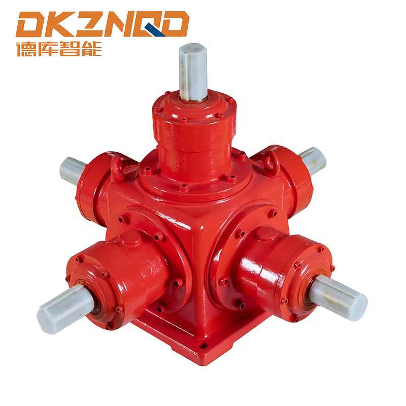
These architectural differences directly influence how electrical parameters are calculated and displayed on the physical spiral bevel gearbox and motor assemblies, dictating everything from mounting bolt patterns to electrical current tolerances during startup phases.
Deconstructing Core Electrical Parameters
The primary electrical parameters printed on a name plate motor dictate how the machine must be connected to the electrical grid or a dedicated variable speed controller. Operating a motor outside these designated voltage, frequency, or phase parameters will result in immediate thermal breakdown or mechanical stall conditions.
Rated Voltage and Operational Tolerances
The rated voltage defines the precise electrical potential at which the motor is designed to achieve optimum performance efficiency. Standard NEMA nameplate ratings frequently feature dual-voltage configurations, such as 230/460V, which indicates the internal stator windings can be reconfigured in either parallel (for lower voltage) or series (for higher voltage) patterns via terminal jumpers.
Most industrial motors are designed to withstand a voltage fluctuation of plus or minus 10 percent from the nominal value stated on the nameplate. However, running a motor continuously at the extreme limits of this tolerance band alters the operational current, increases winding temperatures, and drastically decreases the mechanical efficiency of the system.
Frequency and Phase Configurations
Frequency, measured in Hertz, specifies the alternating current cycle rate of the main supply line. Standard industrial frequencies are rigidly locked to regional grids: 60 Hz is standard throughout North America, whereas 50 Hz regulates networks across Europe, Asia, and South America. Operating a 60 Hz motor on a 50 Hz power supply without reducing the applied voltage will cause severe saturation of the magnetic core, leading to excessive heat generation and immediate loss of torque capacity.
The phase designation identifies the type of alternating current power system required. While single-phase configurations dominate residential and light commercial equipment, industrial environments rely almost exclusively on three-phase systems due to their superior power density, smoother torque delivery, and inherent self-starting capabilities without the need for secondary auxiliary start windings or capacitors.
Understanding Full Load Amperes
When studying how to read motor nameplate values, the current rating is perhaps the most critical calculation metric. The letters fla on a motor nameplate stand for Full Load Amperes. The full load amps definition represents the precise electrical current the motor will draw from the supply line when operating at its full rated output power, nominal voltage, and rated frequency.
FLA acts as the primary baseline value used by electrical engineers to specify the sizing of upstream circuit breakers, terminal contactors, main supply conductors, and thermal overload protection relays. If a motor constantly draws current exceeding its rated FLA value during steady-state operation, it indicates a severe mechanical overload, low line voltage, or a failing internal bearing assembly.
Mechanical Performance and Frame Standards
Mechanical specifications clarify how the motor converts raw electrical power into rotational torque, how fast the shaft rotates under nominal loading conditions, and how the structural housing interfaces with industrial machinery platforms.
| Nameplate Term | Standard Unit | Engineering and Functional Definition |
|---|---|---|
| Rated Horsepower / kW | HP or kW | The mechanical power output capacity delivered at the output shaft without exceeding thermal limits. |
| Full-Load Speed | RPM | The actual rotational velocity of the shaft when operating at full rated load, accounting for rotor slip. |
| Frame Designation | Alphanumeric | Standardized dimension templates detailing shaft height, diameter, length, and mounting bolt spacing. |
| NEMA Design Letter | Letters A, B, C, D | Classification of the motor speed-torque curve and inrush current characteristics during initial startup. |
Rated Horsepower and Synchronous Speed vs. Actual RPM
Motor capacity is measured in Horsepower for NEMA units or Kilowatts for IEC systems. This value represents the mechanical work capacity available at the output shaft. It is critical to differentiate between the synchronous speed of the magnetic field and the actual full-load speed printed on the plate.
The synchronous speed is a theoretical value determined solely by the number of stator poles and the supply frequency. The actual full-load speed, typically recorded as 1725 or 3450 RPM, represents the real velocity of the rotor under load. The numeric difference between the synchronous speed and full-load speed is known as rotor slip, which is essential for generating the electromagnetic torque required to turn the shaft against mechanical resistance.
Operational Insight: When coupling an electric motor to an industrial speed reducer, such as a high-torque spiral bevel gearbox, engineers must base all output torque and mechanical gear ratio calculations on the actual full-load RPM rather than the theoretical synchronous speed to avoid substantial calculation errors in final line speed and torque output.
NEMA Frame Sizes and Enclosure Classifications
The frame designation instantly communicates precise mechanical dimensions. For example, in a standard NEMA 56 frame or 145T frame, the physical code numbers allow technicians to determine the exact centerline height of the shaft, foot mounting hole configurations, and shaft extensions without consulting complex blueprints. Letters appended to frame numbers indicate specific structural variations, such as "T" for modern standard industrial dimensions or "C" for face-mounting configurations commonly used in direct-coupled pump and gear drive applications.
Thermal Characteristics and Insulation Systems
Heat is the primary catalyst for premature electrical insulation breakdown and mechanical bearing failures in industrial motors. Proper interpretation of thermal ratings printed directly on the nameplate prevents catastrophic thermal degradation.
Motor Service Factor Explained
The service factor indicates the continuous overload capacity a motor can safely sustain when operating at its rated voltage and frequency parameters. A motor service factor explained simply means that a machine rated at 10 HP with a service factor of 1.15 can occasionally or continuously handle a maximum load of 11.5 HP under ideal ambient conditions.
However, running a motor continuously within its designated service factor margin carries distinct engineering trade-offs. It increases the steady-state operating temperature, decreases overall operating efficiency, and shortens the long-term lifespan of the internal winding insulation compared to keeping operations strictly within the nominal horsepower thresholds.
Insulation Classes and Ambient Temperature Specifications
The insulation class rating designates the maximum internal winding temperature the electrical wire coatings can withstand before sustaining structural breakdown or chemical degradation. These systems are categorized using standard alphabetical designations:
- Class A: Rated for a maximum internal temperature limit of 105 degrees Celsius. This class is largely obsolete in modern industrial machinery but common in legacy installations.
- Class B: Rated for a maximum internal operational temperature of 130 degrees Celsius. This standard is frequently found in light-duty commercial applications.
- Class F: Rated for a maximum internal operational temperature of 155 degrees Celsius. This is the baseline standard for the vast majority of modern, heavy-duty industrial electric motors.
- Class H: Rated for a maximum internal operational temperature of 180 degrees Celsius. This class is specified for extreme high-heat environments, heavy industrial processing mills, or severe aerospace applications.
This temperature threshold is a cumulative calculation incorporating the standard baseline ambient temperature—typically fixed at 40 degrees Celsius on most nameplates—plus the natural internal thermal rise caused by electrical resistance under full load conditions, combined with a built-in safety margin factor.
Efficiency, Duty Cycles, and Environmental Protection
Modern sustainability criteria and operating cost allocations require rigorous monitoring of motor efficiency metrics and environmental protection boundaries as stated on the manufacturer nameplate layout.
Nominal efficiency values define the percentage of incoming electrical power that is successfully converted into usable mechanical energy at the output shaft, with the remaining energy lost as dissipated heat. NEMA regulations require these values to be explicitly stated as a percentage for all generalized industrial motors. Even a minor two percent increase in nominal motor efficiency can result in substantial cost savings over thousands of operational hours in high-capacity continuous production facilities.
The Duty rating defines the duration for which the motor can operate safely at its full nameplate capacity without requiring a dedicated thermal cooling period. A duty rating marked as "CONT" (Continuous) signifies the motor is designed to operate 24 hours a day, 7 days a week under full load conditions without thermal interruption. Conversely, intermittent duty ratings specify precise operational time blocks, such as 15, 30, or 60 minutes, which are typical for auxiliary crane hoists, valve actuators, or periodic positioning equipment.
Frequently Asked Questions
Q1: What exactly do the letters fla on a motor nameplate stand for?
The letters FLA stand for Full Load Amperes. This value indicates the steady-state electrical current the motor is rated to draw from the incoming power line when operating at its full rated horsepower capacity, nominal design voltage, and rated grid frequency.
Q2: How does a voltage drop impact the full load amps performance of an electric motor?
If the supply voltage drops below the stated nameplate rating, the motor must draw a higher electrical current to deliver the constant mechanical horsepower demanded by the load. This increased current draw leads to excessive heat generation within the internal winding insulation, accelerating thermal breakdown.
Q3: Can a standard industrial motor safely operate continuously within its service factor margin?
While a motor service factor allows continuous operation at an elevated load multiplier (e.g., 1.15), doing so continuously increases operating temperatures, lowers overall electrical efficiency, and can significantly shorten the expected service life of the winding insulation and bearing grease.
Q4: What is the main structural difference between synchronous speed and actual full-load RPM?
Synchronous speed is the theoretical rotational velocity of the stator magnetic field based entirely on supply frequency and the number of physical poles. The full-load RPM is the actual operational speed of the output shaft, which is slightly lower due to rotor slip required to generate output torque.
Q5: Why are some industrial motors stamped with dual-voltage designations like 230/460V?
Dual-voltage ratings indicate the internal stator windings are divided into separate sections that can be wired either in parallel for low-voltage systems (230V) or in series for high-voltage systems (460V), allowing a single motor model to fit different industrial power supply grids.
 05 Jun,2025