ENG
ENG
 English
 русский
 Español
 Türk
Türk
Understanding the Role of Speed Control in Fluid Systems
Industrial manufacturing and fluid processing facilities rely heavily on motorized systems to move liquids, gases, and materials. Historically, these systems operated at a constant speed, relying on mechanical throttling devices such as valves, dampers, or bypass loops to regulate flow and pressure. This traditional approach introduces significant mechanical stress, shortens equipment lifespan, and wastes substantial amounts of electrical energy. To address these operational inefficiencies, modern industrial systems utilize electronic speed control technology to match motor output directly with real-time demand.
In pumping applications, fluid demand fluctuates continuously based on production cycles, system pressure changes, and processing requirements. Running a pump at full speed while choking the output with a control valve is equivalent to driving a vehicle with the accelerator pedal fully depressed while regulating vehicle speed using the brake brake pedal. Electronic speed regulation eliminates this waste by dynamically altering the rotational velocity of the prime mover. This technical analysis explores the core engineering principles of speed control, fluid dynamics, and the integration of precise mechanical drives in heavy-duty applications.
Defining the Technology: What Is a VFD?
When engineering teams encounter industrial fluid systems, the fundamental question often arises: what is a vfd and how does it interface with existing infrastructure? A variable frequency drive, commonly abbreviated as a VFD, is an electronic power conversion device used to regulate the speed and rotational torque of a three-phase induction motor. By manipulating the frequency and voltage of the electrical power supplied to the motor, the drive allows operators to achieve infinitely adjustable speed control across the entire operating range of the driven equipment.
Understanding whats a vfd requires looking beyond simple speed adjustment; it is an intelligent power manager. In typical industrial environments, electrical power is delivered as alternating current at a fixed frequency, typically fifty or sixty hertz. An induction motor connected directly to this line power will rotate at a fixed synchronous speed determined by the number of magnetic poles in the motor stator. A what is a variable frequency drive system breaks this rigid relationship by converting the incoming fixed-frequency AC utility power into a variable-frequency, variable-voltage AC output. This capability transforms a standard fixed-speed motor into an adjustable-speed asset capable of precise process control.
The implementation of variable frequency drives vfds spans across countless industrial domains, including water treatment plants, chemical processing facilities, cooling towers, and oil refineries. Within these environments, a variable frequency drive for pumps serves as the primary mechanism for balancing system hydraulics, preventing water hammer, and minimizing energy consumption. By adjusting motor speed to match exact system curves, these drives eliminate the need for restrictive mechanical valves, enhancing both reliability and process repeatability.
How a Variable Frequency Drive Operates: The Three Internal Stages
The conversion of fixed-frequency utility power to adjustable-frequency output involves three distinct electrical subsystems operating in series inside the drive housing. These stages work sequentially to rectify, filter, and invert the electrical energy, ensuring that the connected motor receives a highly controlled electrical waveform.
The Rectifier Stage
The initial stage consists of a solid-state rectifier bridge that accepts incoming three-phase AC voltage from the utility line. Utilizing an array of high-power diodes or silicon-controlled rectifiers, this stage converts the bidirectional alternating current into unidirectional direct current. This process represents the foundational step of decoupling the motor from the grid frequency.
The DC Bus Filter
The output from the rectifier stage is a pulsating DC voltage that contains significant electrical ripple. The second stage utilizes a massive bank of heavy-duty capacitors, often paired with inductive chokes, to smooth out these fluctuations. This filtered intermediate stage provides a clean, stable reservoir of high-voltage DC power for the final stage of conversion.
The Inverter Stage
The final stage employs high-speed insulated gate bipolar transistors to convert the stable DC bus voltage back into an AC waveform. By switching these transistors on and off thousands of times per second, the drive creates a series of voltage pulses. This technique, known as pulse width modulation, synthesizes a simulated sinusoidal current waveform at the exact frequency and voltage required by the process.
Pumping Dynamics and Variable Speed Operations
To maximize the utility of speed control hardware, engineers must evaluate the specific physical laws governing the driven equipment. Centrifugal pumps, which make up the vast majority of industrial fluid distribution systems, operate under a specific set of physical principles known as the affinity laws. These mathematical relationships dictate how changes in shaft speed influence flow rate, discharge pressure, and brake horsepower.
Under these principles, fluid flow rate changes in direct, linear proportion to a change in shaft speed. However, the discharge pressure or head developed by the pump changes in proportion to the square of the speed change. Most critically, the electrical power consumed by the motor changes in proportion to the cube of the speed change. This cubic relationship forms the mathematical foundation for the exceptional energy-saving capabilities realized through modern motor speed controls.
When utilizing VFD speed control for industrial pumps, even a minor reduction in operational speed yields a disproportionately large reduction in power draw. For instance, reducing a pump motor speed by twenty percent results in a theoretical power requirement reduction of nearly fifty percent. This makes variable speed control infinitely superior to mechanical throttling, where the motor continues to draw full power while fighting against a closed valve, wasting energy as heat and friction within the pump housing.
Quantifiable Advantages of Implementing VFDs in Pumping Infrastructure
Integrating modern power electronics into fluid handling infrastructure provides comprehensive operational advantages that extend far beyond simple energy conservation. These advantages directly impact plant reliability, maintenance budgets, and process precision.
- Substantial Energy Savings: By matching electrical consumption to real-time process demand, facilities eliminate the wasted power inherent in bypass systems and throttling control valves.
- Soft-Starting Capabilities: Electronic control eliminates high inrush current during motor acceleration, preventing localized voltage drops and reducing mechanical shock across the entire drive train.
- Precise Process Regulation: Closed-loop feedback integration allows the drive to adjust speeds dynamically based on pressure, temperature, or flow transmitters, stabilizing the overall process.
- Extended Mechanical Wear Life: Operating at lower speeds reduces wear on pump impellers, mechanical shaft seals, and internal bearings, extending the mean time between failures.
- Elimination of Water Hammer: Programmed acceleration and deceleration ramps prevent sudden velocity changes within pipeline systems, preventing catastrophic pressure surges.
The table below highlights the operational differences between traditional fixed-speed pumping systems and modernized variable frequency drive installations across critical engineering parameters.
| Operational Parameter | Fixed Speed with Throttling Valve | Variable Frequency Drive Control |
|---|---|---|
| Motor Energy Consumption | Remains high regardless of actual fluid flow requirements | Scales cubically with motor speed reductions |
| Starting Current Inrush | Up to six to eight times normal full-load current | Controlled acceleration; never exceeds full-load rating |
| Mechanical Stress on Seals | High due to backpressure and constant top-speed operation | Minimized due to reduced shaft velocities and low vibration |
| System Pressure Management | Regulated via mechanical restriction; prone to sudden spikes | Maintained smoothly via electronic feedback loops |
| System Power Factor | Degrades significantly under reduced mechanical loading | Maintained at a high level across the entire operational range |
Torque Classification and Alternative Industrial Applications
Industrial machinery loads are generally categorized into two main types based on their torque requirements: variable torque and constant torque. Centrifugal pumps and fans represent variable torque loads, where the torque required increases with the square of the speed. In contrast, positive displacement pumps, conveyor systems, reciprocating mixers, and compressors require identical torque regardless of operational speed.
Implementing constant torque VFD applications requires distinct engineering specifications compared to standard centrifugal pump installations. For constant torque loads, the drive must provide a consistent current output across its entire frequency range to ensure the motor can overcome resistance at low speeds without overheating. Heavy-duty industrial mixers or positive displacement pumps rely on these specialized settings to handle high-viscosity fluids without stalling during low-speed cycles.
Similarly, a variable frequency drive compressor represents another common constant torque application found throughout industrial manufacturing plants. Air compressors face rapidly changing air demands throughout a production shift. Using an adjustable speed drive allows the compressor to modulate its rotational velocity to maintain a perfectly stable system air pressure, eliminating the highly inefficient start-stop cycles or continuous unloaded idling typical of standard compressor control schemes.
Mechanical Drive Synergy: Coupling VFDs with High-Efficiency Gearing
While electronic speed control optimizes the electrical input to a motor, the mechanical transmission system responsible for delivering that power to the driven equipment must be equally optimized. High-demand industrial systems require robust mechanical components capable of handling variable rotational speeds, reversing loads, and high torque profiles without compromising overall system efficiency.
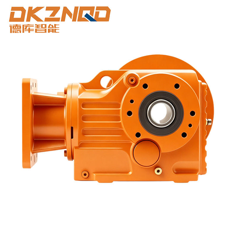
The image below illustrates a typical high-performance industrial gearmotor configuration designed to handle demanding variable speed profiles and maintain mechanical efficiency in harsh operating environments.
When a motor slows down under electronic speed control, its internal cooling fan slows down as well, which can lead to heat buildup if the motor operates at high torque for extended periods. Utilizing a high-efficiency helical bevel gear reducer allows the motor to operate within its optimal RPM band while providing the necessary mechanical speed reduction at the output shaft. This synergy protects electrical components from thermal degradation while delivering maximum mechanical reliability to the overall plant process.
Calculating Energy Saving with VFD Drives: A Real-World Scenario
To fully justify the capital investment required to deploy electronic speed control systems, plant engineering teams must evaluate the long-term financial impacts. The financial viability of these installations becomes evident when looking at energy saving with VFD drives over an extended operational timeline.
Consider an industrial cooling water pump driven by a ninety kilowatt induction motor that runs continuously throughout the year. In a standard installation using a mechanical throttling valve, the motor draws approximately ninety-two kilowatts of electrical power from the grid continuously to overcome system friction and throttling restrictions. At standard industrial utility rates, the continuous operation of this unmodulated asset represents a substantial baseline operating cost.
If the system is retrofitted with an electronic speed drive and the average required flow rate drops to eighty percent of maximum capacity for half of the operating year, the power requirement drops substantially. According to the centrifugal pump affinity laws, operating at eighty percent speed reduces the required electrical power to approximately forty-seven percent of the full-load rating. The following analytical table demonstrates the annual power consumption and financial implications of this speed reduction strategy.
| Operational Metric per Annum | Traditional Throttling System | Variable Speed Controlled System |
|---|---|---|
| High Flow Operational Period (100% Speed) | 4380 Hours at 92 kW | 4380 Hours at 93 kW (includes drive loss) |
| Low Flow Operational Period (80% Speed) | 4380 Hours at 92 kW | 4380 Hours at 44 kW |
| Total Annual Electrical Energy Consumed | 805920 Kilowatt-Hours | 600060 Kilowatt-Hours |
| Net Energy Savings Achieved | Baseline Reference Value | 205860 Kilowatt-Hours Saved Annually |
| Reduction in Operating Costs | 0% Reduction | Approximately 25% Reduction in Power Costs |
This calculated scenario highlights the financial benefits realized when applying speed modulation to fluid handling processes. In addition to direct electrical savings, the reduction in system operating hours at maximum pressure extends mechanical component lifespans, lowers facility maintenance costs, and minimizes unplanned production downtime.
Frequently Asked Questions Concerning Variable Frequency Drives
Q1: Can any standard industrial AC induction motor be operated with a variable frequency drive?
Most modern three-phase AC induction motors can operate with an electronic speed control drive. However, older motors or motors designed without adequate insulation may experience insulation degradation due to the rapid voltage spikes generated by pulse width modulation switching. For optimal reliability, motors should meet standard industry specifications for inverter-duty performance, ensuring high-temperature insulation and appropriate bearing protection are integrated into the design.
Q2: What is the minimum speed at which an industrial pump can safely run using a VFD?
The minimum operational speed depends entirely on the design of the pump and the motor cooling method. Centrifugal pumps generally should not run below the speed required to overcome static system head pressure, as operating below this point results in a zero-flow condition that can overheat the pump. From a motor perspective, standard totally enclosed fan-cooled motors lose cooling efficiency at low speeds. If continuous low-speed operation is required, an auxiliary constant-speed cooling fan or a high-efficiency gear reducer should be utilized.
Q3: How do variable speed drives affect the overall power factor of an industrial plant?
Standard AC induction motors cause the power factor to degrade significantly when operating below their rated mechanical load. When an electronic speed drive is installed, the diode rectifier bridge on the input side maintains a high displacement power factor, typically above ninety-five percent, across the entire speed and load range. This high performance shields industrial facilities from the utility penalties associated with low power factor operations.
Q4: What is the primary operational distinction between a soft starter and a VFD?
A soft starter is used exclusively to control motor current and torque during the initial startup phase, reducing mechanical shock by gradually ramping up voltage before locking into standard grid speed. A variable frequency drive provides this exact same soft-starting capability but maintains full control over motor speed and torque throughout the entire operational cycle, allowing continuous adjustment during production.
 05 Jun,2025