ENG
ENG
 English
 русский
 Español
 Türk
Türk
What Is a Worm Gearbox?
A worm gearbox is a type of speed reducer that uses a worm (a screw-like gear) meshing with a worm wheel to transmit power between non-intersecting, perpendicular shafts. The core function is to achieve high reduction ratios in a compact space — often ranging from 5:1 to 100:1 in a single stage — while also providing self-locking capability in many configurations.
In industrial practice, worm gearboxes are widely used in conveyor systems, packaging machinery, elevators, mixers, and material handling equipment. Their ability to reduce speed significantly while multiplying torque makes them indispensable in applications where controlled, low-speed motion is required.
How Does a Worm Gearbox Work?
The operating principle relies on the helical threading of the worm engaging the teeth of the worm wheel. As the worm rotates (driven by a motor), its threads push against the worm wheel teeth, causing the wheel to rotate at a much lower speed. The ratio of teeth on the worm wheel to the number of starts (threads) on the worm determines the gear reduction ratio.
- Single-start worm: One thread. If the worm wheel has 40 teeth, the ratio is 40:1.
- Double-start worm: Two threads. Same 40-tooth wheel gives a 20:1 ratio.
- Quadruple-start worm: Four threads. Ratio becomes 10:1.
The angle of the worm thread (lead angle) directly affects efficiency and self-locking behavior. A lead angle below approximately 6° tends to produce self-locking, meaning the worm wheel cannot back-drive the worm — an important safety feature in lifting or holding applications.
Power transmission in a worm gearbox involves sliding contact between the worm and wheel, which generates more heat and friction than gear types using rolling contact. This is why proper lubrication is critical — most worm gearboxes require oil bath or splash lubrication to maintain efficiency and extend service life.
Key Components of a Worm Gearbox
Worm Shaft
The worm is a cylindrical gear with one or more helical threads. It is typically made from hardened alloy steel to withstand wear from the sliding mesh. The worm is connected directly to the input shaft (motor side).
Worm Wheel (Worm Gear)
The worm wheel meshes with the worm and is usually made from bronze or cast iron. Bronze is preferred in high-load applications because it reduces friction against the steel worm and dissipates heat more effectively. A typical worm wheel has between 20 and 100 teeth.
Housing and Bearings
The housing (casing) supports both the worm shaft and worm wheel, maintains proper shaft alignment, and contains the lubricant. Bearings inside the housing absorb axial and radial loads. Most housings are made from cast iron or aluminum alloy.
Output Shaft
The output shaft is connected to the worm wheel and delivers the reduced-speed, high-torque output to the driven machine. Output shaft configurations can include hollow bore, solid shaft, or flange-mounted depending on the application.
Worm Gearbox Efficiency and Reduction Ratios
Efficiency is one of the most important performance parameters. Due to the sliding nature of worm gear contact, efficiency is lower than helical or spur gearboxes. Typical efficiency values are:
| Reduction Ratio | Typical Efficiency (%) | Typical Lead Angle |
|---|---|---|
| 5:1 – 10:1 | 80% – 90% | High (15°–25°) |
| 15:1 – 30:1 | 70% – 80% | Medium (8°–15°) |
| 40:1 – 60:1 | 55% – 70% | Low (4°–8°) |
| 60:1 – 100:1 | 40% – 60% | Very Low (<6°) |
At high reduction ratios, efficiency drops significantly. This is a known trade-off: higher ratios provide greater torque multiplication but produce more heat per unit of power transmitted. Thermal management (housing fins, forced cooling, or oil coolers) becomes important in continuous-duty high-ratio applications.
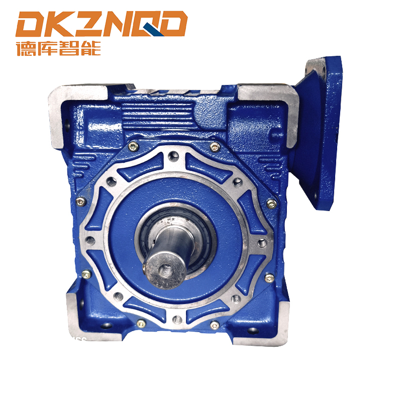
What Is an RV Worm Gear Reducer?
An RV Worm Gear Reducer is a specific design variant of worm gearbox widely adopted in industrial automation, robotics, and general machinery. "RV" refers to the compact, right-angle housing configuration (also known as a face-mounted or flange-type reducer) with a hollow or solid output shaft.
Key features of RV worm gear reducers include:
- Compact right-angle design: Input and output shafts are at 90°, saving installation space.
- Aluminum alloy housing: Lightweight construction suitable for light-to-medium duty cycles.
- Wide ratio range: Typically available from 7.5:1 to 100:1 in a single stage.
- Standardized mounting: Compatible with standard IEC motor flanges, simplifying integration.
- Self-locking capability: At ratios above approximately 40:1, the unit becomes self-locking, preventing back-drive under static load.
RV worm gear reducers are available in multiple sizes — commonly designated by center distance, such as RV 25, RV 30, RV 40, RV 50, RV 63, RV 75, RV 110, and RV 130. Each size handles a different output torque range. For example, an RV 63 unit typically delivers output torques up to approximately 200 N·m, while an RV 110 can handle up to 500 N·m or more depending on ratio and duty cycle.
Worm Gearbox vs. Other Reducer Types
Choosing the right reducer type depends on application requirements. Here is a direct comparison:
| Feature | Worm Gearbox | Helical Gearbox | Bevel Gearbox |
|---|---|---|---|
| Shaft Angle | 90° (perpendicular) | Parallel | 90° (intersecting) |
| Efficiency | 40% – 90% | 95% – 99% | 90% – 98% |
| Reduction Ratio (single stage) | 5:1 – 100:1 | 3:1 – 10:1 | 3:1 – 6:1 |
| Self-Locking | Yes (at low lead angles) | No | No |
| Noise Level | Low | Moderate | Low to Moderate |
| Cost | Low to Medium | Medium to High | High |
| Typical Use | Conveyors, lifts, mixers | High-efficiency drives | Right-angle high-torque |
Worm gearboxes excel when a high reduction ratio, self-locking behavior, and compact right-angle output are all needed simultaneously — conditions where no other single gearbox type is as cost-effective.
Typical Applications of Worm Gearboxes
Worm gearboxes appear across a broad range of industries due to their unique combination of features:
- Conveyor systems: Speed reduction and directional change in a single unit, with self-locking preventing belt rollback when stopped.
- Packaging machinery: Compact drives for filling, sealing, and labeling machines where precise, low-speed output is required.
- Lifting and hoisting: Self-locking at high ratios prevents load drop in the event of power failure.
- Mixers and agitators: High torque at low output RPM for stirring viscous materials.
- Gate and valve actuators: Smooth, controlled operation with high torque for opening and closing industrial valves.
- Solar tracking systems: Precise angular positioning with self-locking to hold panel position without continuous power.
Lubrication and Maintenance of Worm Gearboxes
Due to the sliding contact between worm and wheel, correct lubrication directly determines efficiency, temperature rise, and service life. Key maintenance points:
- Oil type: Most manufacturers specify ISO VG 220 or ISO VG 460 mineral gear oil, or synthetic polyglycol (PAG) oil for high-efficiency requirements.
- Oil level: Maintain the oil level at the sight glass or fill plug mark. Running low causes accelerated wear on the bronze worm wheel.
- Oil change interval: Typically every 5,000 – 10,000 hours of operation, or at least once every 2 years.
- Operating temperature: Normal continuous operating temperature should stay below 80°C. Above 90°C, thermal overload protection or additional cooling should be considered.
- Shaft seals: Inspect lip seals periodically for oil leakage. Seal replacement is a low-cost preventive measure that avoids major failures.
For units that operate intermittently (duty cycle under 25%), grease lubrication may be acceptable, but continuous-duty applications almost always require oil bath lubrication for adequate heat dissipation.
How to Select the Right Worm Gearbox
Proper selection requires evaluating several parameters together:
- Required output torque: Calculate the load torque at the output shaft and apply a service factor (typically 1.25–2.0) based on shock loading, daily operating hours, and start/stop frequency.
- Reduction ratio: Determine the required output RPM from the input motor speed. For example, a 1,450 RPM motor with a 50:1 ratio delivers 29 RPM output.
- Mounting orientation: Worm gearboxes can be mounted in multiple positions (horizontal worm, vertical worm-up, vertical worm-down). Oil fill and drain port locations change with orientation.
- Thermal rating: Verify the gearbox thermal power rating matches continuous-duty requirements. If not, specify a larger housing size or add external cooling.
- Self-locking requirement: If the application requires holding a load without a brake, select a ratio that guarantees self-locking (typically ≥40:1 for standard lead angles).
FAQ
Q1: What is the difference between a worm gear and a worm gearbox?
A worm gear refers to the worm wheel component (the toothed gear that meshes with the worm). A worm gearbox is the complete assembly, including the worm shaft, worm wheel, housing, bearings, seals, and output shaft.
Q2: Can a worm gearbox be back-driven?
It depends on the lead angle. At lead angles below approximately 6° (typically ratios above 40:1), most worm gearboxes are self-locking and cannot be back-driven. At higher lead angles (lower ratios), back-driving is possible.
Q3: Why does a worm gearbox get hot during operation?
Sliding contact between the worm and wheel generates heat due to friction. Higher reduction ratios and continuous operation increase heat buildup. Proper lubrication, correct oil level, and adequate housing surface area are the primary ways to manage operating temperature.
Q4: What is the typical service life of a worm gearbox?
With proper lubrication and correct sizing, a worm gearbox typically achieves 15,000 – 30,000 hours of service life. The worm wheel (bronze) is usually the first component to wear and is replaceable without replacing the full unit.
Q5: What does the "RV" designation mean in an RV worm gear reducer?
RV designates a compact, right-angle worm gear reducer with a hollow or solid output shaft and face-mounted housing. The RV series is a widely standardized product family available in multiple frame sizes to cover different torque requirements.
Q6: Can a worm gearbox be used in both horizontal and vertical mounting positions?
Yes, but the mounting orientation affects oil fill levels and lubrication requirements. Always consult the manufacturer's mounting guidelines and adjust the oil fill quantity accordingly to ensure proper lubrication in all positions.
Q7: How do I calculate the output torque of a worm gearbox?
Multiply the input torque by the gear ratio, then multiply by the gearbox efficiency. For example, an input torque of 10 N·m, a ratio of 50:1, and an efficiency of 70% yields an output torque of approximately 350 N·m. Always apply an appropriate service factor for your specific load conditions.
 05 Jun,2025