

 ENG
ENG
 English
 русский
 Español
 Türk
Türk


The most important fact to understand before selecting or replacing a helical gear is simple: right-handed and left-handed helices deliver the same torque and the same efficiency. Their only practical difference is the direction of the axial thrust generated during rotation. In a helical gearbox, that direction controls the bearing load path and, ultimately, the service life of the unit.
When you remove the inspection cover from an industrial helical gear motor, the slant of the teeth tells you which hand you have. A right-handed tooth trace runs from lower left to upper right. A left-handed trace runs from lower right to upper left. This simple observation is enough to explain why a replacement pinion that looks perfectly similar can still fail on the first day.
What Determines the Handedness of a Helix
A helix is a curve that spirals around a cylinder at a fixed angle. The concept of handedness comes from the right-hand rule: place your right thumb along the axis of the helix and curl your fingers in the direction of the spiral. If your fingers follow the path of the helix as it moves away from you, the helix is right-handed. If the path follows your left hand instead, the helix is left-handed.
Nature provides vivid examples of both forms. The double-helix structure of DNA is right-handed. The alpha-helix in proteins is also right-handed when formed from L-amino acids. In a completely different field, the threads of a standard wood screw follow a right-handed helix, while some machine screws use left-handed threads for specialized fastening tasks.
Helical gear teeth obey the same geometric logic. A gear cutter removes material along a helical path, leaving a tooth trace that wraps around the gear blank. The handedness of that trace is fixed during manufacturing. To identify the handedness of a helical gear, look at the gear face. If the tooth line runs from the lower-left corner toward the upper-right corner, the helix is right-handed. If it runs from the lower-right corner toward the upper-left corner, the helix is left-handed.
Right-Handed vs Left-Handed Helical Gears
Both hand variants satisfy the same kinematic requirement: they transmit motion and torque between parallel or crossed axes while delivering a higher contact ratio than straight spur gears. The difference is not in power capacity. It is in the direction of the axial force that arises from the inclined contact line.
| Feature | Right-Handed Helix | Left-Handed Helix |
|---|---|---|
| Tooth trace on the gear face | From lower left to upper right | From lower right to upper left |
| Axial thrust with clockwise rotation | Toward the observer | Away from the observer |
| Axial thrust with counterclockwise rotation | Away from the observer | Toward the observer |
| Mating gear in an external mesh | Must be left-handed | Must be right-handed |
| Typical use in industrial reducers | Widely used | Widely used |
The table above explains why a gearbox cannot simply use two gears of the same hand. For an external gear pair, the pinion and the gear must be of opposite hands. If both were right-handed, the teeth would bind. This pairing rule is one of the simplest and most consequential points in helical gear design.
The axial force direction becomes especially important when torque reverses. A reversible application, such as a conveyor that runs in both directions, sees the axial thrust reverse every time the motor starts in the opposite direction. The bearing arrangement must therefore handle thrust in both directions. This is why standard industrial helical gearmotors often pair a deep-groove ball bearing with an angular contact bearing or a tapered roller bearing on the output shaft.
Why Handedness Matters in Gearbox Design and Selection
In a single helical gear stage, the handedness is not a quality specification. It is a configuration parameter. Its effect, however, cascades through the entire shaft and bearing system.
Axial Load Paths
The inclined teeth generate an axial force proportional to the transmitted torque and the tangent of the helix angle. A typical industrial helical stage uses a helix angle between 15 and 30 degrees, so the axial force can be 30% or more of the tangential force. This force must be absorbed by a bearing. If the housing or bearing arrangement assumes the force enters the bearing in one direction, the wrong tooth hand pushes the shaft the other way, overloading the bearing and creating a rubbing contact on the housing face.
Procurement Risk
When an OEM or a maintenance team orders a replacement pinion, the wrong handedness leads to immediate problems. The gear mesh still engages, but the axial force direction is reversed. The resulting vibration, axial wobble, and heating are often mistaken for a bearing problem. In practice, the parts are swapped back, and the correct left- or right-handed helix restores smooth operation.
Double-Helical Alternatives
In heavy industrial units, designers cancel the axial thrust by cutting two opposite-hand helix segments side by side on the same gear body. This herringbone or double-helical arrangement is effective but more expensive. For standard gearmotors below a few hundred kilowatts, a single helical stage with proper thrust bearings is the standard solution. This is why the helix angle and helix direction are selected as a matched pair during the design of an R Series helical geared motor.
 R Series Single-Stage Helical Geared Motor for High-Speed ApplicationsOffering 12 gearbox sizes with 1- to 3-stage options, this unit delivers up to 160 kW and 18,000 Nm, with output speeds reaching 1,075 r/min, ideal for high-speed duties.View Product →
Practical Considerations for Helical Gearbox Applications
When an application goes from the drawing board to the installation floor, the risk of a handedness error is low if you follow a short checklist.
- Rotation direction. Define the normal operating rotation of the output shaft. For one-directional loads, the supplier can choose the helix hand so the axial thrust pushes the pinion toward the heavy-duty side of the housing. For reversible loads, both directions must be acceptable.
- Mounting position. A gearbox can be mounted in six standard positions, M1 through M6. In each position, gravity and the axial thrust direction interact. A configuration that works on a floor-mounted unit may create an unexpected thrust vector on a shaft-mounted unit.
- Multi-stage interaction. In a right-angle unit, the bevel stage and the helical stage both generate axial loads. The net axial load at a shaft must combine their directions. When the unit is assembled, the thrust-bearing arrangement is matched to this combined load.
- Hypoid gear sets. A hypoid gear reducer uses teeth with a curved lengthwise form and an axis offset. The handedness of the hypoid pinion defines the offset direction of the gear set. The installed configuration must follow the product drawing.
- Replacement orders. When ordering a replacement gear only, record the gear markings, the gearbox size, the mounting position, and the output rotation. With those four inputs, an engineering team can confirm the correct left- or right-handed helix before the part is cut.
For right-angle drives where the output shaft is perpendicular to the motor, a K Series helical bevel gearmotor combines a helical stage with a spiral bevel stage. The tooth direction of the bevel stage must be matched to the application layout, so the same unit footprint can be supplied in left or right configurations.
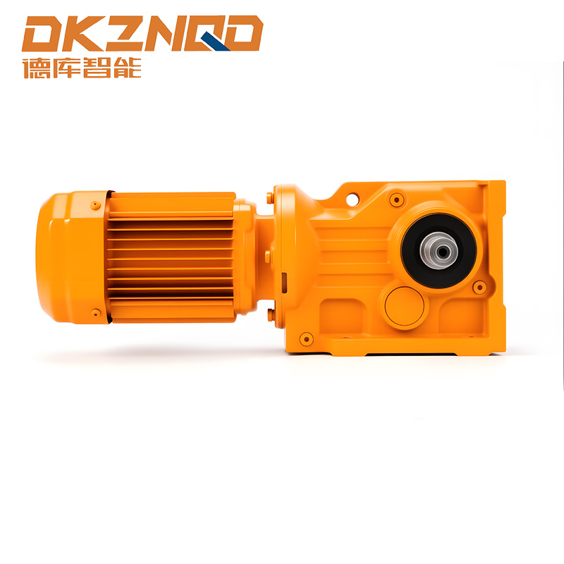 K Series Helical Bevel Gearmotor for Right-Angle DrivesAvailable in 12 sizes with power up to 200 kW and torque to 50,000 Nm, this right-angle gearmotor features compact structure, low noise, and long service life for space-limited installations.View Product →
When a low-noise, high-torque solution with an offset axis is preferred, a BKM hypoid gear reducer uses a different tooth arrangement where the helix direction controls the offset direction. This allows the gearbox to reach high reductions with a compact axial distance.
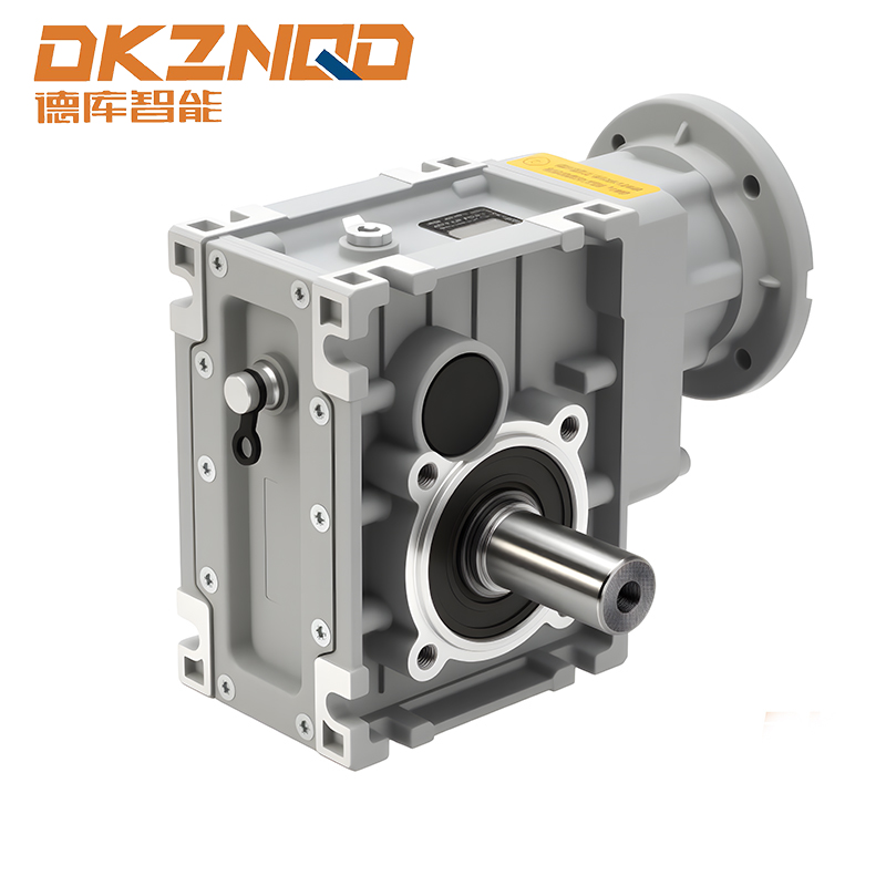 BKM Hypoid Gear Reducer with High Efficiency and Compact DesignWith 5 models offering 2- or 3-stage reduction, power 0.12–5.5 kW and torque to 750 Nm, this hypoid reducer exceeds 90% efficiency, reducing energy loss and fitting all orientations.View Product →
Anchoring the discussion in practical criteria makes the handedness question useful rather than abstract. For many buyers, the most efficient route is to review a detailed guide on helical gear motor selection before making the final specification.
How to Identify the Handedness of an Installed Gear
Field identification is straightforward with a clear line of sight. Remove the inspection cover, rotate the gear slightly, and observe the tooth trace from the front face of the gear.
- Look directly at the gear face with the axis pointing away from you.
- Check the start of the tooth at the bottom of the face and move your eye along the tooth toward the top.
- If the tooth line moves from lower left to upper right, the gear is right-handed.
- If the tooth line moves from lower right to upper left, the gear is left-handed.
- Confirm by applying the right-hand rule along the shaft axis to the known direction of the tooth trace.
Another practical check is the contact pattern. When a gear pair meshes correctly, the contact area runs across the tooth flank in a diagonal line. The angle of that line matches the base helix angle. If the contact pattern appears on the opposite diagonal direction, the pair is mismatched, and edge loading is likely.
What to Keep in Mind
Right-handed and left-handed helices are both normal and necessary in industrial transmission systems. Neither has an inherent performance advantage. The practical risk comes from a mismatch between the gear hand and the mounting configuration.
Take five simple actions before a final order is released.
- Confirm the output rotation direction in the running state.
- Select the mounting position and any shaft orientation constraints.
- State whether the application is reversible or one-directional.
- Ask for the axial thrust direction at each shaft from the manufacturer.
- Keep the replacement part data complete: gearbox model, gear ratio, and gear hand or part number.
If a gearbox is already installed and the tooth hand is unclear, an engineering review of the unit and the application is the fastest path to certainty. The cost of installing the wrong replacement part can far exceed the cost of a few minutes of verification.
For a clearer look at the internal gear arrangement, the working principle of a reducer explains how helical stages, shafts, and bearings are organized in a standard unit.
Q1: Does handedness affect the price of a helical gearbox?
No. Both hands are produced on the same manufacturing lines with the same tolerances and materials. The cost difference only appears in engineered double-helical configurations for high-power applications.
Q2: Can I reverse a helical gearbox by reversing the motor direction?
Yes, but the axial thrust direction also reverses. The bearings and shaft configuration must be designed for bidirectional axial load. Standard industrial gearmotors usually are, but always verify with the manufacturer for the specific mounting position.
The bottom line is simple: when you choose or replace a helical gearmotor, handedness is a design decision, not a failure mode. A correctly matched handedness will quietly deliver torque for years. A mismatched one will shorten bearing life and generate noise within days of commissioning.
 05 Jun,2025